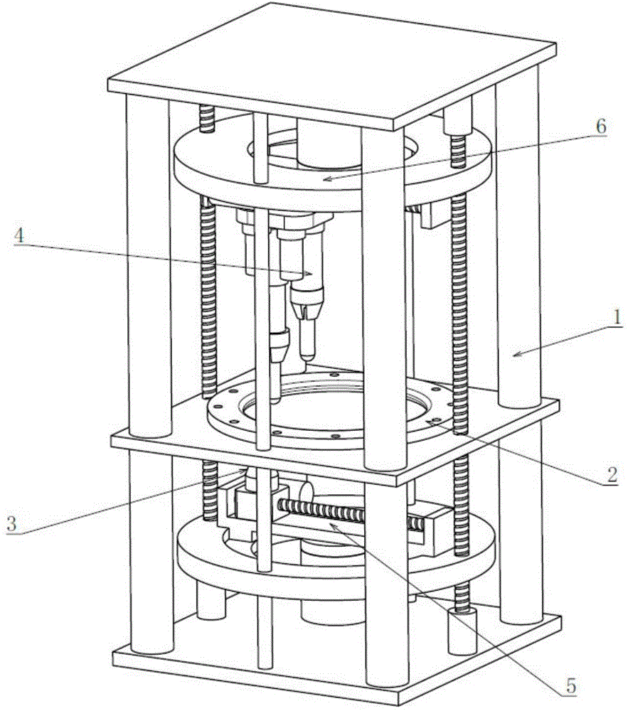
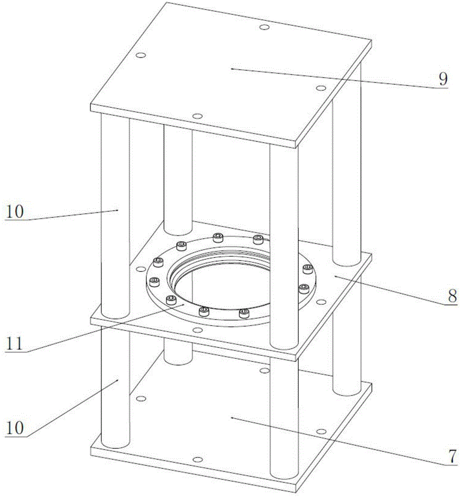
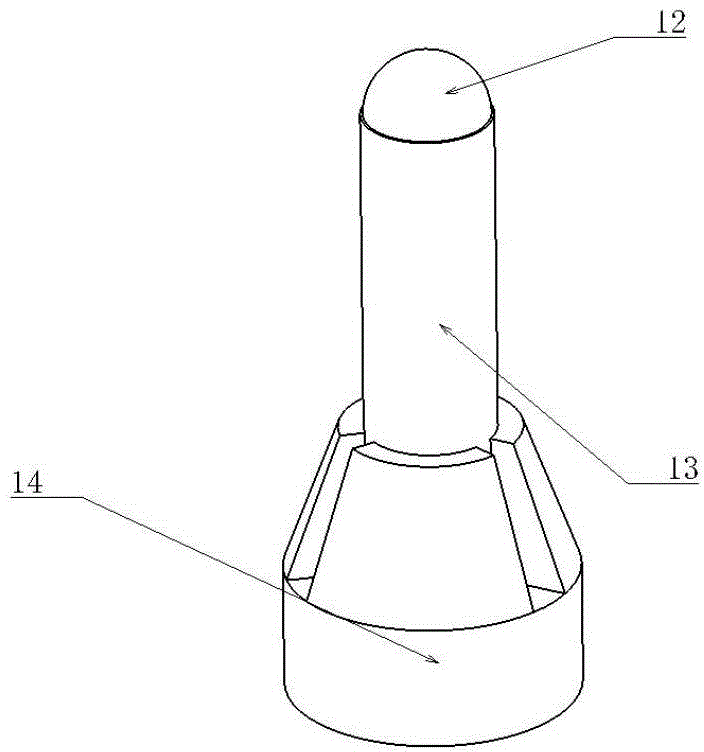
Plate double-side three-point incremental forming device
An incremental forming and plate technology, applied in the field of plate plastic forming, can solve the problems of large forming force, limited forming shape, unadjustable distance between indenters, etc., and achieve the effect of improving efficiency, good modularization and compact structure
- Summary
- Abstract
- Description
- Claims
- Application Information
AI Technical Summary
Problems solved by technology
Method used
Image
Examples
Embodiment 1
[0027] Double-sided double-point forming: suitable for small-scale forming
[0028] Such as Image 6 As shown, the first tool head 16 and the lower tool head 3 in the upper duplex tool head 4 participate in forming. The telescopic screw rod 18 of the second tool head 17 near the center of the plate of the double-link tool head before forming is shortened to the shortest, and the first tool head 16 on the outside is slightly elongated. During forming, only the first tool head 16 and the lower tool head 3 are jointly formed. The forming trajectory is a contour trajectory. After the upper and lower tool heads adjust their radial positions, the lower tool head 3 moves up, and the upper first tool head 16 moves down. After reaching the forming position, the upper and lower tool heads start to rotate synchronously. The vertical and radial directions of the tool head do not move. After one round of forming is completed, the lower tool head 3 moves down, and the upper duplex tool h...
Embodiment 2
[0030] Tool head movement, double-sided three-point incremental forming for simultaneous forming and shaping:
[0031] Such as Figure 7 As shown, the two tool heads 16, 17 of the upper double tool head 4 and the lower tool head 3 are all involved in the forming, the lower tool head 3 plays a supporting role at the bend of the sheet, and the second tool head 17 at the lower position is on the sheet. forming, while the upper first tool head 16 shapes the sheet in the formed area while increasing support stiffness. Before forming, the telescopic screw rods 18 of the two tool heads are adjusted to corresponding lengths according to the forming shape, and both points can contact the sheet material after being pressed down. During forming, the lower tool head 3 presses up, and the upper duplex tool head 4 presses down. The subsequent forming process is similar to the first forming method.
Embodiment 3
[0033] Local convex double-sided three-point incremental forming:
[0034] Such as Figure 8 As shown, the two tool heads 16, 17 of the upper double tool head 4 and the lower tool head 3 are all involved in forming, the lower tool head 3 acts on the upper protrusion, and the two tool heads 16, 17 of the double tool head 4 act On the inside and outside of the lower tool head, the sheet is formed into a convex structure. Before forming, the telescopic screw rods 18 of the two tool heads are adjusted to corresponding lengths according to the forming shape, and both points can contact the sheet material after being pressed down. During forming, the lower tool head 3 presses up, and the upper duplex tool head 4 presses down. The subsequent forming process is similar to the first forming method.
PUM
 Abstract
Description
Claims
Application Information
 - R&D
- Intellectual Property
- Life Sciences
- Materials
- Tech Scout
- Unparalleled Data Quality
- Higher Quality Content
- 60% Fewer Hallucinations
Browse by: Latest US Patents, China's latest patents, Technical Efficacy Thesaurus, Application Domain, Technology Topic, Popular Technical Reports.
© 2025 PatSnap. All rights reserved.Legal|Privacy policy|Modern Slavery Act Transparency Statement|Sitemap|About US| Contact US: help@patsnap.com


