Manual self-centering clamp for thin-walled part

A technology for self-centering fixtures and thin-walled parts, which is applied in the direction of workpieces, manufacturing tools, toolholder accessories, etc., can solve the problems of thin-walled long parts clamping and processing deformation, etc., and achieve high positioning accuracy, simple structure, and convenient loading and unloading Effect

Inactive Publication Date: 2015-08-26
张鸿来
View PDF1 Cites 19 Cited by
  • Summary
  • Abstract
  • Description
  • Claims
  • Application Information

AI Technical Summary

Problems solved by technology

[0003] The present invention aims to solve the technical problem of clamping deformation of thin-walled long parts, and provides a manual self-centering fixture for thin-walled parts

Method used


Image

  • Manual self-centering clamp for thin-walled part
  • Manual self-centering clamp for thin-walled part
  • Manual self-centering clamp for thin-walled part

Examples


Embodiment Construction

[0010] The present invention will be further described below in conjunction with the accompanying drawings and embodiments.

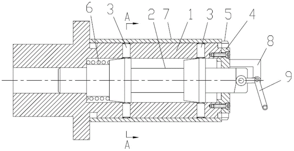
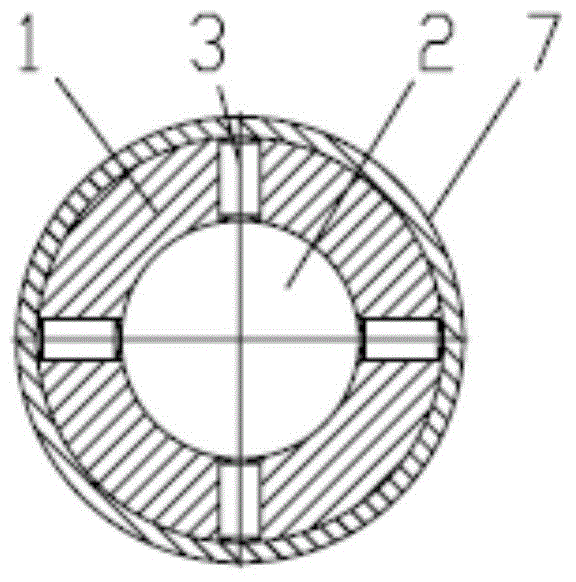
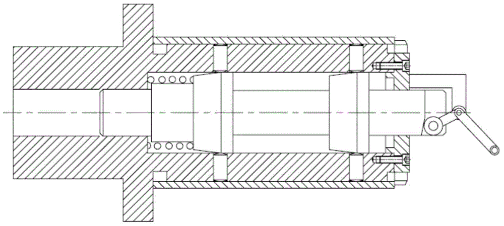
[0011] Such as Figure 1 to Figure 3 As shown, a manual self-centering fixture for thin-walled parts includes a mandrel 1, a multi-stage taper shaft 2, a positioning clamping column 3, an end cover 4, an end compression nut 5, a return spring 6, a connecting seat 8, a manual drive rod 9.

[0012] One end of the positioning column of the mandrel 1 is provided with a positioning step, the outer circle of the mandrel 1 is a positioning cylinder, a stepped inner hole is arranged in the positioning cylinder of the mandrel 1, and at least two A group of radial through holes, each group of radial through holes has three or four radial through holes evenly distributed on the same cross section of the positioning column, the radial through holes are movable and connected to the positioning clamping column, and the mandrel 1 The multi-stage cone shaft 2 is mova...


PUM


Abstract

The invention relates to a manual self-centering clamp for a thin-walled part. The manual self-centering clamp is characterized in that at least two groups of radial through holes are formed in a positioning column of a mandrel in the axial direction; each group of radial through holes comprise three or four radial through holes uniformly distributed in the same cross section of the positioning column; positioning clamping columns are connected into the radial through holes in a clearance fit manner; a multi-stage cone shaft is connected into a step inner hole of the mandrel in a clearance fit manner; a reset spring connected onto the multi-stage cone shaft in a sleeving manner is mounted between a boss at the front end of the multi-stage cone shaft and the front-end step surface of the step inner hole; the rear end of the multi-stage cone shaft is connected with an inner hole of an end cover in a clearance fit manner, and the end cover is fixedly connected onto the rear end of the positioning column; conical columns corresponding to the groups of radial through holes are arranged in the middle of the multi-stage cone shaft; each conical column comprises a front-end circular truncated cone and a rear-end circular truncated cone; the conical column surface of each conical column is contacted and connected with the bottom end of the corresponding positioning clamping column; a connecting base is arranged on the end cover; a manual driving rod is mounted in the connecting base; the driving end of the manual driving rod is contacted and connected with the bottom surface of a groove in the rear end of the multi-stage cone shaft.

Description

technical field [0001] The invention relates to a centering fixture for thin-walled parts, in particular to a self-centering fixture for thin-walled parts. Background technique [0002] In mechanical processing, some workpieces are positioned and clamped through their inner holes, but the existing fixtures either have complex structures, or are troublesome to unload, and most of them cannot achieve self-centering, and often cannot meet the conditions Requirements, resulting in poor machining accuracy. Therefore, the Chinese invention patent application number: 201110286659.4 discloses a self-centering fixture. The end of the blue plate has a section of external thread, and the section of external thread is equipped with an adjusting nut. A slidable retaining ring is sleeved on the outer circumference of the mandrel, and a pair of chutes are arranged on the mandrel. There is a pull rod in the center suspension, one end of the pull rod is fixed with the retaining ring by a p...

Claims


Application Information

Patent Timeline
IPC IPC(8): B23B31/40
CPCB23B31/4073B23B31/4046B23B31/4066B23B2215/64
Inventor 张鸿来
Owner 张鸿来
Why Eureka
Try Eureka