Self-centering clamp for thin-walled part

A technology for self-centering fixtures and thin-walled parts, which is applied in the direction of metal processing machinery parts, clamping, and workpieces. It can solve problems such as clamping and processing deformation of thin-walled parts, and achieve improved processing accuracy, small deformation, and easy loading and unloading. The effect of machining parts

Inactive Publication Date: 2015-08-26
张鸿来
View PDF1 Cites 12 Cited by
  • Summary
  • Abstract
  • Description
  • Claims
  • Application Information

AI Technical Summary

Problems solved by technology

[0003] The present invention aims to solve the technical problem of clamping deformation of thin-walled parts, and provides a self-centering fixture for thin-walled parts

Method used


Image

  • Self-centering clamp for thin-walled part
  • Self-centering clamp for thin-walled part
  • Self-centering clamp for thin-walled part

Examples


Embodiment Construction

[0011] The present invention will be further described below in conjunction with the accompanying drawings and embodiments.

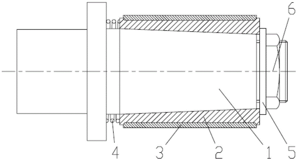
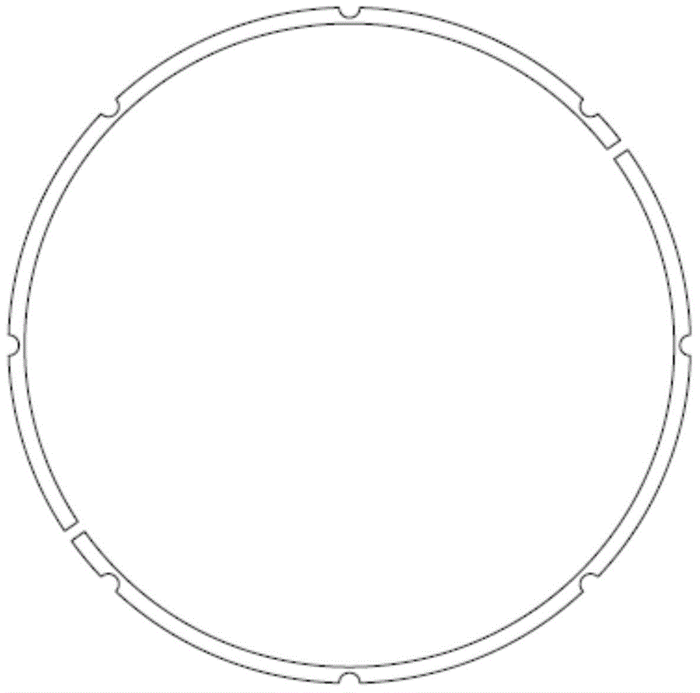
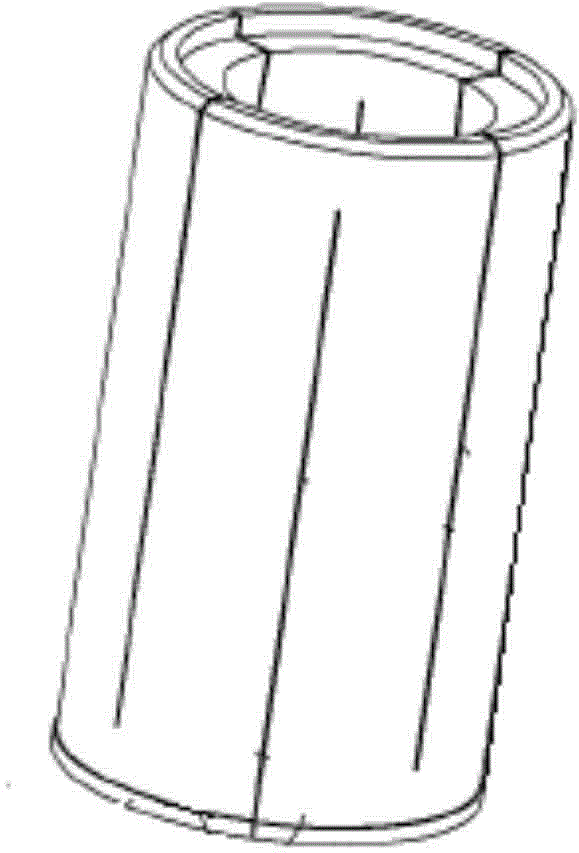
[0012] Such as figure 1 , Shown in 4, a self-centering fixture for thin-walled parts, including a mandrel 1, expansion sleeve 2, flexible positioning sleeve 3, spring 4, retaining ring 5, adjustment nut 6.

[0013] The mandrel 1 is in the shape of a cone, the inner wall of the expansion sleeve 2 is a conical surface matching the outer wall of the mandrel, and the outer wall is a cylindrical surface, and the expansion sleeve 2 is matched with the cone of the mandrel 1 through the conical surface of the inner wall. The front end of the sleeve 2 is connected to the stepped end face of the rear end of the mandrel 1 through the spring 4, the rear end of the expansion sleeve 2 is in contact with the adjusting nut 6 screwed on the threaded end of the mandrel through the stop ring 5, and the expansion sleeve 2 is externally connected with a flexible positioning...


PUM


Abstract

The invention relates to a self-centering clamp for a thin-walled part. The self-centering clamp comprises a mandrel, an expanding sleeve, an adjusting nut and a retaining ring, wherein the mandrel adopts a conical body; the inner wall of the expanding sleeve adopts a conical surface matched with the outer wall of the mandrel, and the outer wall of the expanding sleeve is a cylindrical surface; the expanding sleeve is matched and connected with the conical body of the mandrel through the conical surface of the inner wall; the front end of the expanding sleeve is connected with the step end surface at the rear end of the mandrel through a spring; the rear end of the expanding sleeve is contacted and connected with the adjusting nut through the retaining ring, and the adjusting nut is screwed at the threaded end of the mandrel; the expanding sleeve is sleeved with a flexible positioning sleeve. The self-centering clamp for the thin-walled part is simple in structure, workpieces are convenient to load and unload, self-centering can be realized, particularly, after the flexible positioning sleeve is used, the deformation of the thin-walled part is small in the machining process of clamping the thin-walled part, the machining precision is improved, and the coaxiality and the perpendicularity of the machined thin-walled part can be guaranteed; the expanding sleeve is loosened by the spring, so that the part is convenient to load, unload and machine.

Description

technical field [0001] The invention relates to a workpiece fixture, in particular to a self-centering fixture. Background technique [0002] In mechanical processing, some workpieces are positioned and clamped through their inner holes, but the existing fixtures either have complex structures, or are troublesome to unload, and most of them cannot achieve self-centering, and often cannot meet the conditions Requirements, resulting in poor machining accuracy. Therefore, the Chinese invention patent application number: 201110286659.4 discloses a self-centering fixture. The end of the blue plate has a section of external thread, and the section of external thread is equipped with an adjusting nut. A slidable retaining ring is sleeved on the outer circumference of the mandrel, and a pair of chutes are arranged on the mandrel. There is a pull rod in the center suspension, one end of the pull rod is fixed with the retaining ring by a pin, the pin is passed through a pair of slid...

Claims


Application Information

Patent Timeline
Patent Type & Authority Applications(China)
IPC IPC(8): B23Q3/12
CPCB23B31/4013B23B2215/64
Inventor 张鸿来
Owner 张鸿来
Why Eureka
Try Eureka