

Machining method and machining equipment for parts with curved surfaces
A technology of curved surface parts and processing methods, which is applied in the processing of large-size curved surface parts and the field of processing equipment for curved surface parts, can solve the problems of poor precision, high cost, and large floor space, and achieve the goal of improving processing accuracy and reducing processing errors Effect
- Summary
- Abstract
- Description
- Claims
- Application Information
AI Technical Summary
Problems solved by technology
Method used
Image

Examples
Embodiment 1
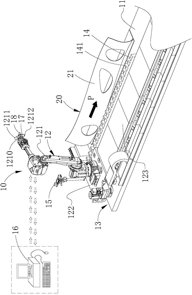
[0085] see Figure 1 to Figure 4 , the processing method of the curved surface part of the present embodiment will be described below.
[0086] The processing method of the curved surface part of the present embodiment comprises the following steps:
[0087] Step S101, prepare n curved surface parts 20 to be processed, and n≥2, any curved surface part 20 has at least one processing surface 21, and set a processing direction for processing the processing surface 21 on the processing surface 21, wherein , the processing direction is shown by arrow P;
[0088] Step S102, setting a first placement area 11 for the curved surface part 20 to be docked and placed;
[0089] Step S103, placing the curved part 20 on the first placement area 11;
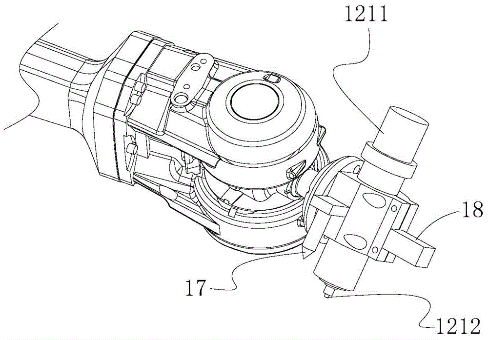
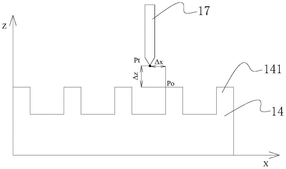
[0090] Step S104, prepare a robot 12 for processing the curved surface parts 20, set the robot 12 to include a robot body 121 and a control unit (not shown) for controlling the work of the robot body 121, so that the robot body 121 is equippe...
Embodiment 2
[0110] see Figure 5 and Figure 6 , and combined with figure 1 and figure 2 , the processing method of the curved surface part of the present embodiment will be described below.
[0111] The processing method of the curved surface part of the present embodiment comprises the following steps:
[0112] Step S201, preparing n curved surface parts 20 to be processed, and n≥2, any curved surface part 20 has at least one processing surface 21, and setting a processing direction for processing the processing surface 21 on the processing surface 21, Wherein, the processing direction is shown by arrow P;
[0113] Step S202, setting a first placement area 11 for the curved surface part 20 to be docked and placed;
[0114] Step S203, setting a curved part 20 on the first placement area 11;
[0115] Step S204, prepare a robot 12 that can move in segments to process the curved surface parts 20 in segments, set the robot 12 to include a robot body 121 and a control unit (not shown) ...
PUM
 Abstract
Description
Claims
Application Information