Bi-directional inverted grinding method for full molded surface of blade with two ends having tip shrouds

A grinding process and blade technology, which is applied in the direction of grinding workpiece support, metal processing equipment, grinding/polishing equipment, etc., can solve the problems of unfavorable mass production of blades, low processing efficiency, difficult blades, etc., and improve blade processing Efficiency, the effect of improving machining accuracy and machining efficiency

Active Publication Date: 2015-08-26
枣庄北航机床创新研究院有限公司
View PDF7 Cites 6 Cited by
  • Summary
  • Abstract
  • Description
  • Claims
  • Application Information

AI Technical Summary

Problems solved by technology

At present, this type of blade can only be milled by a five-axis linkage machine tool with A and B rotary motion axes. At this time, the blade is installed horizontally on the A axis of the rotary motion axis of the machine tool. The average angle centerline of the normal of the midpoint of the end edge plate. At this time, the normals of the centers of the two edge plates may be different. It is beneficial to use the 3 to 4 axis machine tool to directly take the angle bisector of these two normal vectors. The blade is processed, which may be different from the connection of the center of gravity of the blade body section line) and the rotary motion axis of the machine tool is basically parallel, and the two ends of the blade are fixedly connected with the t

Method used


Image

  • Bi-directional inverted grinding method for full molded surface of blade with two ends having tip shrouds
  • Bi-directional inverted grinding method for full molded surface of blade with two ends having tip shrouds
  • Bi-directional inverted grinding method for full molded surface of blade with two ends having tip shrouds

Examples


Embodiment Construction

[0018] The double-ended crowned blade of the present invention can also be referred to as a blade. The following describes the single-blade clamping and grinding embodiment of the present invention with reference to the accompanying drawings.

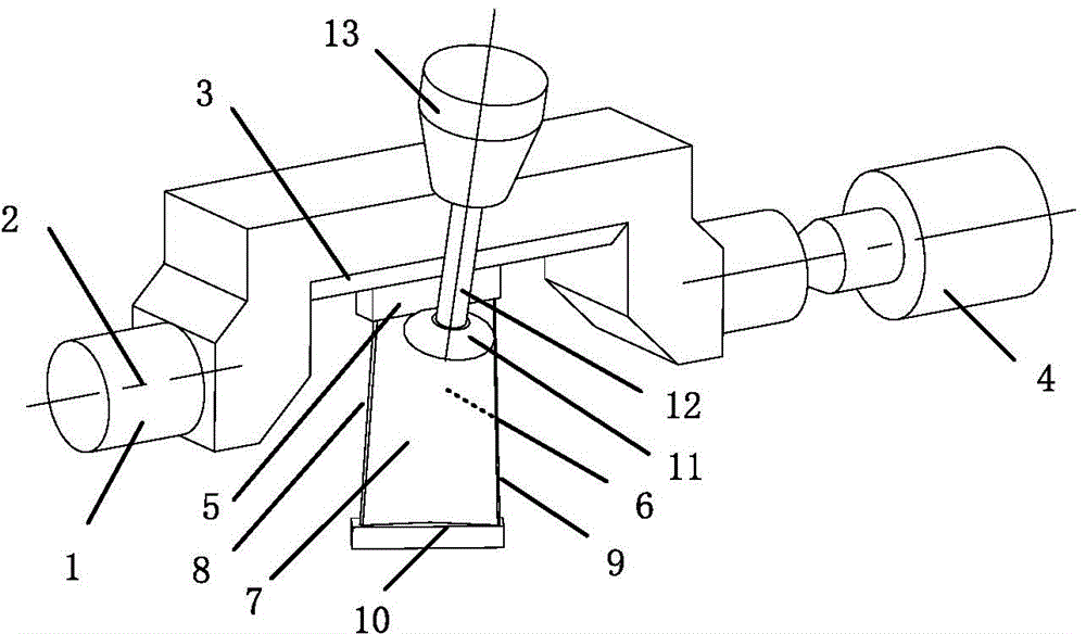
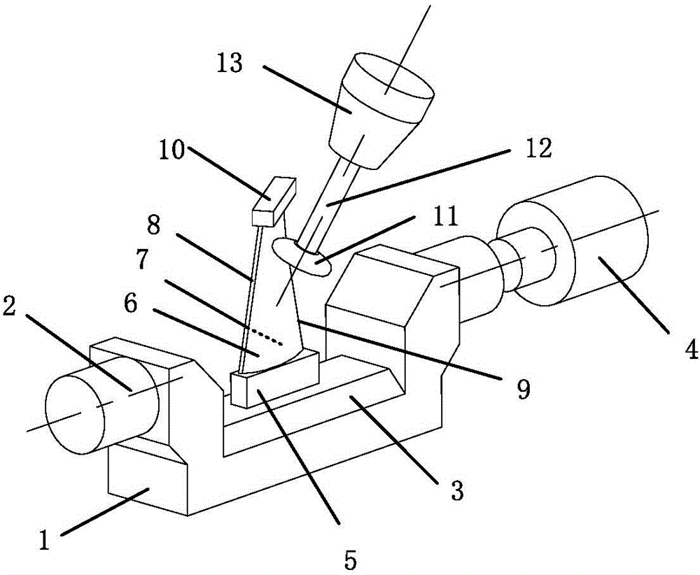
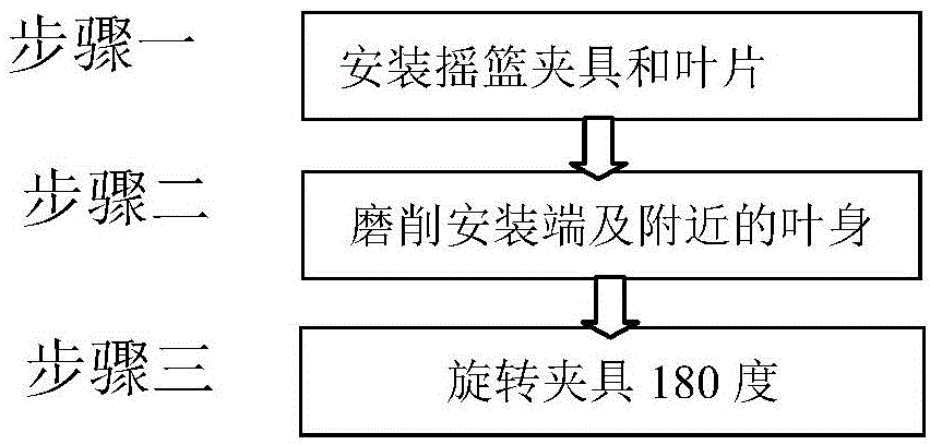
[0019] See figure 1 — image 3 , the present invention is a kind of double-ended crown blade full profile rotary inverted grinding method, the specific steps of the method are as follows:

[0020] Step 1: Choose a five-axis linkage machine tool with A / B axis, and install a cradle-like fixture on it. One end of the fixture is connected to the A-axis of the machine tool and rotated by the A-axis. The other end can be supported by the center hole Or use the other A-axis of the dual A-axis for support, ensuring that the cradle grip rotates with the A-axis. The cradle clamp generally has a bow-shaped structure, so that the middle part deviates from the center of the A-axis. At this time, the blade can be installed vertically in the neutral...


PUM


Abstract

Provided is a bi-directional inverted grinding method for a full molded surface of a blade with two ends having tip shrouds. The bi-directional inverted grinding method comprises three steps: step 1, selecting a five-axis linkage machine tool having A/B axes, installing a cradle-like fixture having one end connected to an A axis and driven to rotate by the A axis and having the other end supported by a center hole for ensuring rotation between the cradle-like fixture and the A axis; step 2, selecting a dished circular-ring-surface grinding wheel for machining the blade surface of a blade installing end, a blade root transition surface and a tenon so that an included angel formed between the connecting line from the installing end of the blade to a cantilever end and the positive direction of a machine tool Z axis is an obtuse angle; step 3, enabling the cradle-like fixture to drive the blade to rotate for 180 degrees after the blade body part close to the installing end is finished machining such that the cantilever end of the blade faces upwards and the included angel formed between the blade body direction and the positive direction of the machine tool Z axis is an acute angle, and in the meantime, grinding a blade pot of the blade, a blade back and leading and exhaust edge portions of the blade. In the step 1, some portions of the cradle-like fixture deviate from of the center of the A axis and the center of the blade body draws close to the rotary center of the A axis as much as possible.

Description

technical field [0001] The invention relates to a full-profile grinding method of a blade, in particular to a method of using a five-axis linkage machine tool to perform full-profile bidirectional inverted grinding of a double-ended crowned blade, and belongs to the technical field of blade processing. Background technique [0002] At present, many stator blades of aero-engines have double-sided edge plates, and the outer sides of the edge plates are usually equipped with journals or tenons or blade crowns. The blades with structures such as tenons or blade crowns at both ends can be called double-ended. Crowned blade, the blade has at least one tenon end, for the stator blade, this part is connected to the engine case, so the installation radius is large, it can be called the outer end, and the other end is called the inner end. In terms of rigidity, the blade near the outer end has a large thickness and good rigidity, which can be used as the installation end of cantilever...

Claims


Application Information

Patent Timeline
IPC IPC(8): B24B19/14B24B41/06
CPCB24B19/14B24B41/06
Inventor 陈志同罗杨宁涛李勋张云
Owner 枣庄北航机床创新研究院有限公司
Why Eureka
Try Eureka