Degassing rotor structure with sealed gas accumulation function

A rotor structure and gas storage technology, applied in the field of aluminum alloy smelting equipment, can solve the problems that the bubble pressure cannot be completely uniform, the gas storage chamber is not completely closed, and the bubble shear is uneven, and achieves a good degassing effect. , The effect of shortening the degassing time and the short processing time

Inactive Publication Date: 2015-08-26
SUZHOU MINGZHI TECH
View PDF5 Cites 4 Cited by
  • Summary
  • Abstract
  • Description
  • Claims
  • Application Information

AI Technical Summary

Problems solved by technology

The degassing rotor for on-line refining hides the stirring teeth, reduces surface turbulence during high-speed rotation, and optimizes the size of the box cavity. In the scheme, on the one hand, the air storage chamber of the degassing rotor is not completely closed, the internal air flow is unstable, and the pressure of the formed bubbles cannot be completely uniform; on the other hand, after the rotor is worn or oxidized, the shape of the air storage chamber or The size will also change, which will easily cause the problem of uneven shearing of the bubbles and the decrease of degassing efficiency

Method used


Image

  • Degassing rotor structure with sealed gas accumulation function
  • Degassing rotor structure with sealed gas accumulation function
  • Degassing rotor structure with sealed gas accumulation function

Examples


Embodiment 1

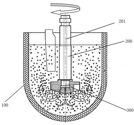
[0027] Embodiment one: see Figure 1 to Figure 3 , as shown in the legend therein, a degassing rotor structure with sealed gas storage is set in a crucible 100 , and the degassing rotor structure includes a rotating rod 200 and a disk-shaped rotating disk 300 .

[0028] The rotating rod 200 has a first end and a second end. The body of the rotating rod 200 is provided with an air intake passage 201, the first end is provided with an external thread, and the second end is connected to the driving device (not shown in the figure). connect;

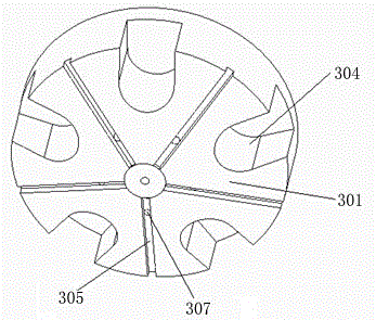
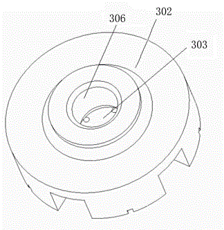
[0029] The turntable 300 has a first end face 301 and a second end face 302. The disc body of the turntable 300 is provided with an air storage chamber 303 located at the center and not connected to the first end face 301. The first end face 301 is in the shape of a truncated conical protrusion. The first end surface 301 is provided with five dividing grooves 304 uniformly distributed in the circumferential direction and extending along the...

Embodiment 2

[0038] The rest is the same as the first embodiment, except that the cone angle of the first end surface is 135 degrees.

Embodiment 3

[0040]The rest is the same as the first embodiment, except that the cone angle of the first end surface is 150 degrees.


PUM

PropertyMeasurementUnit
angleaaaaaaaaaa

Abstract

The invention discloses a degassing rotor structure with a sealed gas accumulation function. The degassing rotor structure comprises a rotating rod and a rotor body, wherein a gas inlet channel is formed in the rotating rod; the rotor body is a disc-like rotating table; the rotating table comprises a first end surface and a second end surface; a plurality of gas outlet grooves are formed in the first end surface; a gas accumulation cavity which is positioned in the center of the first end surface but not communicated with the first end surface is formed in the table body of the rotating table, communicated with the gas inlet channel through a gas inlet hole in the second end surface, and communicated with the gas outlet grooves through a plurality of gas outlet channels distributed uniformly in the circular direction. On one hand, gas flow in the gas accumulation cavity is stable, and gas passes through the uniformly distributed gas outlet channels, is distributed into all the gas outlet grooves under uniform pressure, and then is subjected to uniform shearing to form bubbles, so that the purpose of efficient degassing can be fulfilled; on the other hand, the gas accumulation cavity is prevented from being impacted by the abrasion of the rotor body, impact on the degassing effect is avoided, and the blockage possibilities of the gas outlet channels are low.

Description

technical field [0001] The invention relates to equipment for smelting aluminum alloys, in particular to a degassing rotor structure for performing degassing treatment during the smelting of aluminum alloys. Background technique [0002] During the smelting process of aluminum alloy, due to the reaction of molten aluminum with oxygen and water vapor, oxidized inclusions and hydrogen gas are produced, which have many adverse effects on the subsequent smelting process. To solve this problem, the current common process is to use inert gas diffusion method, chlorine gas or mixed gas diffusion method to achieve the purpose of hydrogen removal and slag removal. Both of the above two processes need to use the degassing rotor to introduce gas into the aluminum alloy melt: the degassing rotor rotates at a high speed while introducing gas into the aluminum alloy melt. After the gas overflows from the bottom of the degassing rotor, it diffuses around. It is crushed into smaller bubble...

Claims


Application Information

Patent Timeline
Patent Type & Authority Applications(China)
IPC IPC(8): C22B9/05C22B21/06C22C1/02C22C21/00
Inventor 吴伟强
Owner SUZHOU MINGZHI TECH
Why Eureka
Try Eureka