
Automatic cleaning water storage pool

An automatic cleaning and storage tank technology, which is applied in the configuration of water supply tanks, water supply devices, cleaning hollow objects, etc., can solve the problems of increased cleaning work of the storage tank, humid and hot storage tanks, and inability to clean the storage tank, etc. To achieve the effect of reducing resistance, reducing weight and facilitating discharge

Active Publication Date: 2015-08-26
NANTONG HONGFENG ELECTRO MECHANIC
View PDF8 Cites 1 Cited by
  • Summary
  • Abstract
  • Description
  • Claims
  • Application Information

AI Technical Summary

Problems solved by technology

[0004] At present, most of the cleaning work of the reservoir is manual cleaning, and the cleaning personnel must enter the reservoir for cleaning, which is time-consuming and laborious, and there are many humid and stuffy phenomena in the reservoir, which makes the cleaning of the reservoir more difficult
However, the existing automatic cleaning equipment cannot effectively clean the reservoir due to the existence of cleaning dead angles.

Method used


Image

  • Automatic cleaning water storage pool
  • Automatic cleaning water storage pool
  • Automatic cleaning water storage pool

Examples


Embodiment 1

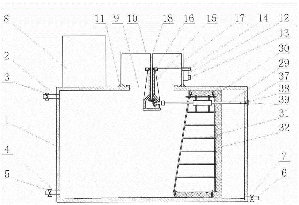
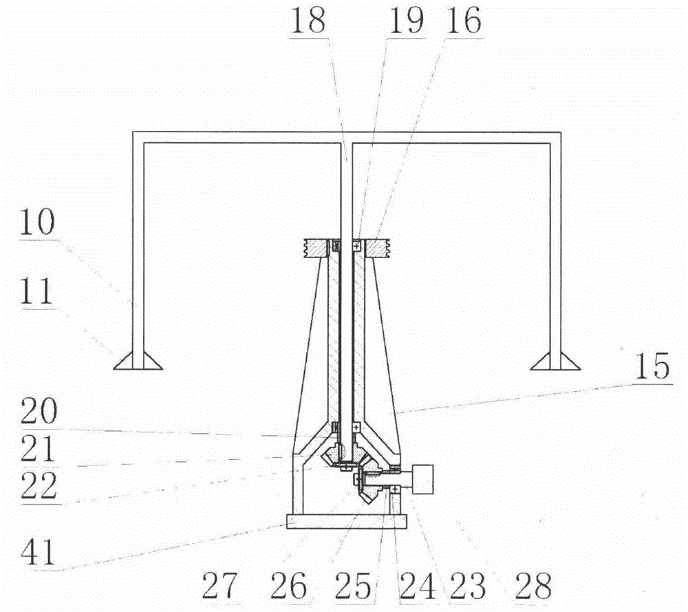
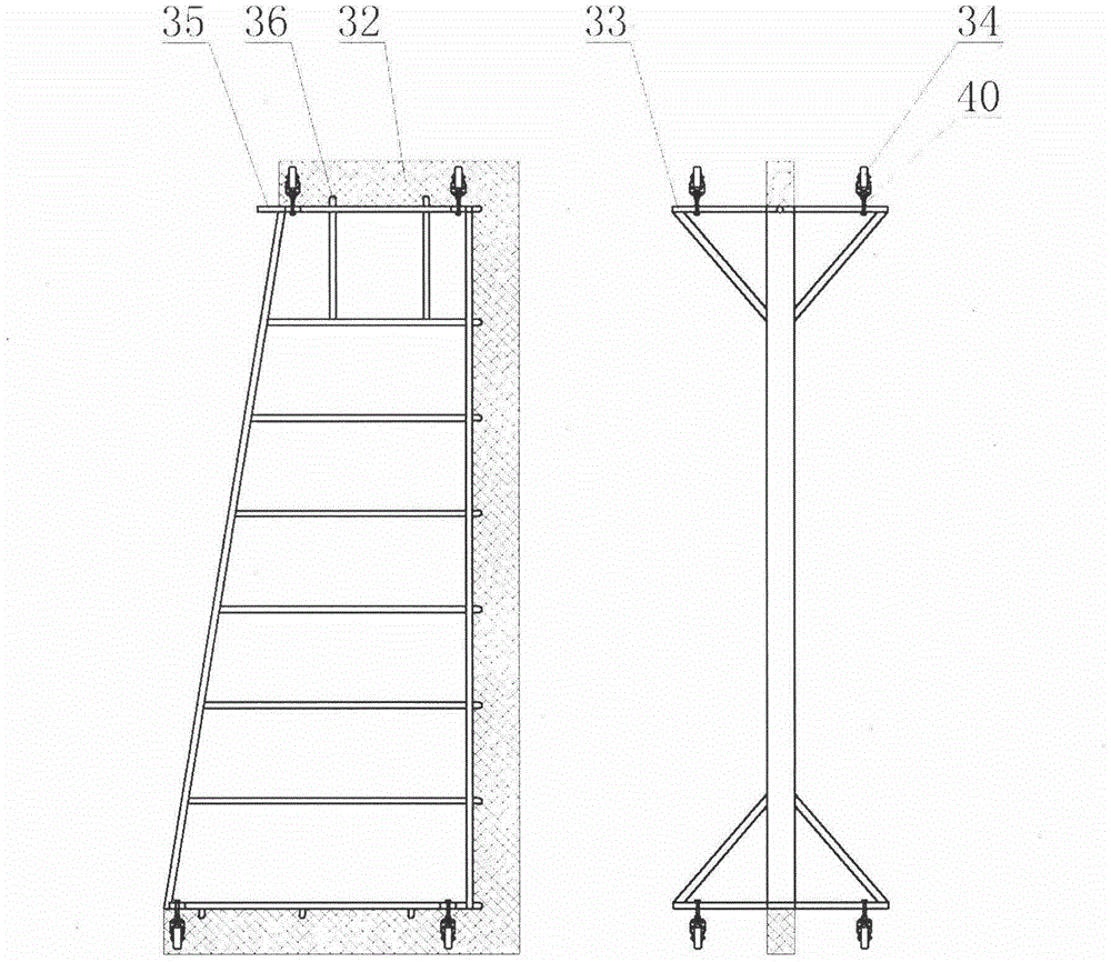
[0033] Embodiment 1, the water storage tank is a cylindrical airtight structure, which can effectively prevent rainwater, dust and other sundries from falling into the water storage tank. The upper part of the water storage tank is provided with a water inlet, and the water inlet is provided with a water inlet valve. The lower part of the water storage tank is provided with a water outlet, the water outlet is provided with a water outlet valve, the bottom of the water storage tank is provided with a sewage outlet, the sewage outlet is provided with a sewage discharge valve, and a small spare pool, which can provide water source for cleaning the reservoir, and ensure non-stop water during cleaning; the top of the reservoir is provided with a manhole, the top of the manhole is provided with a bracket, and the bottom of the bracket is provided with a foot support, and the bracket passes through The bolts in the foundation support are fixed on the top of the reservoir; a motor is s...

Embodiment 2

[0034] Embodiment 2, the storage tank is a cylindrical airtight structure, which can effectively prevent rainwater, dust and other sundries from falling into the storage tank; the bottom surface of the storage tank is a spherical surface with a high middle and low surroundings, which can better collect dirt. To facilitate the discharge of sewage; the upper part of the reservoir is provided with a water inlet, the water inlet is provided with a water inlet valve, the lower part of the reservoir is provided with a water outlet, and the water outlet is provided with a water outlet valve, and the water storage The bottom of the pool is provided with a sewage outlet, the sewage outlet is provided with a sewage valve, and a small spare pool is provided above the reservoir, which can provide water for cleaning the reservoir and ensure non-stop water during cleaning; the water reservoir The top of the pool is provided with a manhole, the top of the manhole is provided with a bracket, t...


PUM


Abstract

The invention discloses an automatic cleaning water storage pool, and mainly relates to the field of storing tap water. The automatic cleaning water storage pool comprises a water storage pool body, a support, an electromotor, a transmission device and a cleaning frame, a small stand-by pool is arranged at the top of the water storage pool body, a manhole is formed in the water storage pool body, the support is arranged at the top of the manhole, the electromotor is arranged on the support, a fixing shaft is arranged on the support and connected with the transmission device which is composed of bevel gears, a lead screw and a screw nut, the transmission device is connected with the cleaning frame, and the electromotor can drive the cleaning frame to rotate along the fixing shaft and move along the lead screw through the transmission device. The automatic cleaning water storage pool has the advantages that the automatic cleaning water storage pool can replace manual labor to clean the water storage pool, the cleaning frame can be taken out from the water storage pool after cleaning, sundries such as rain water and dust can be effectively prevented from falling into the water storage pool, the operation is easy, the structure is stable, the installation is convenient, dirt is easy to collect, cleaning is conducted effectively, cleaning dead angles do not exist, and water can be supplied while cleaning.

Description

technical field [0001] The invention relates to the field of tap water storage, in particular to an automatic cleaning reservoir. Background technique [0002] The cistern is the storage facility for the "finished water" of the waterworks, and the "finished water" flows directly to thousands of households through the water supply network. Therefore, the sanitation of the cistern plays an important role in ensuring the quality of the factory water. Due to the limited pressure of the water supply pipe network, most high-rise buildings need secondary water supply, that is, the tap water is first stored in the reservoir, and then pumped to the residents' homes. With the rapid increase of high-rise buildings, secondary water supply has become the main way of water supply in my country's cities. [0003] The reservoir is easy to breed moss and microorganisms, and rainwater and foreign matter will enter if it is not tightly sealed. If it is not cleaned and disinfected in time, it ...

Claims


Application Information

Patent Timeline
IPC IPC(8): E03B11/00B08B9/087B08B9/093
CPCB08B9/087B08B9/093E03B11/00
Inventor 卢云飞
Owner NANTONG HONGFENG ELECTRO MECHANIC
Learn More