A variable-hole row-spacing impingement film cooling structure for the nozzle wall

A film cooling and wall surface technology, which is applied to jet propulsion devices, machines/engines, etc., can solve the problems of small drop, the infrared radiation suppression effect needs to be improved, and the overall cooling of the wall surface temperature has not been realized, so as to improve the impact cooling efficiency and enhance the Wall-adhesive effect, uniform cooling distribution effect on the wall surface

Inactive Publication Date: 2017-05-17
NANJING UNIV OF AERONAUTICS & ASTRONAUTICS
View PDF6 Cites 0 Cited by
  • Summary
  • Abstract
  • Description
  • Claims
  • Application Information

AI Technical Summary

Problems solved by technology

Although this technology reduces the wall surface temperature to a certain extent, the drop rate is small, and the overall cooling of the wall surface temperature has not been realized, so the infrared radiation suppression effect needs to be improved

Method used


Image

  • A variable-hole row-spacing impingement film cooling structure for the nozzle wall
  • A variable-hole row-spacing impingement film cooling structure for the nozzle wall
  • A variable-hole row-spacing impingement film cooling structure for the nozzle wall

Examples


Embodiment Construction

[0025] The present invention will be further described below in conjunction with the accompanying drawings and embodiments.

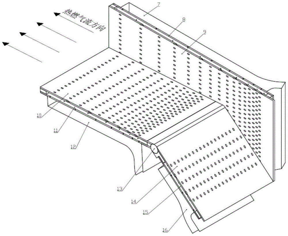
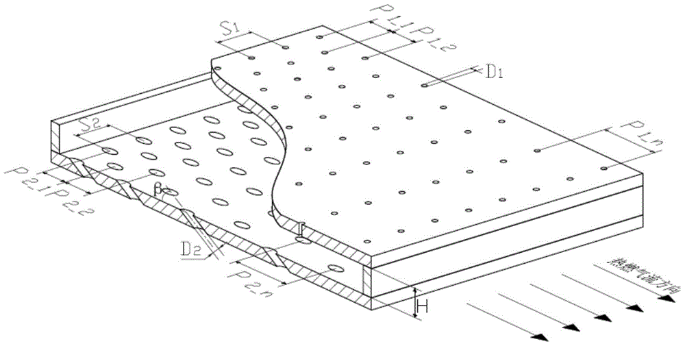
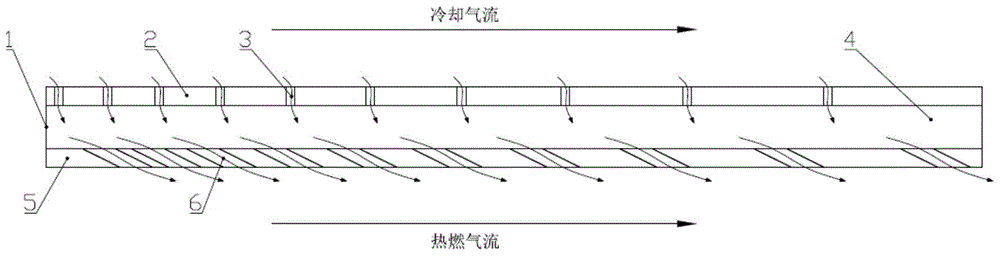
[0026] Please refer to Figure 1 to Figure 3 As shown, the impingement film cooling structure with variable hole row pitch applied to the nozzle wall of the present invention mainly includes an end wall 1 , an outer side wall 2 and an inner side wall 5 . The end wall 1 connects the outer wall 2 and the inner wall 5 to form a cooling chamber 4, the outer wall 2 is provided with an impact hole 3, and the inner wall 5 is provided with a gas film hole 6; the impact hole 3 is a circular hole with a diameter of D. 1 , which is consistent with the normal direction of the outer wall surface; the air film hole 6 is a circular hole with a diameter of D 2 , forms a certain deflection angle β with the normal direction of the inner wall surface, and the deflection direction is consistent with the hot gas flow direction; the row spacing of the impact holes 3 is den...


PUM


Abstract

The invention discloses an impingement and air-film cooling structure adopting variable-hole array pitches used for a wall surface of a jet tube. The impingement and air-film cooling structure comprises an end wall, an outer side wall and an inner side wall. Impingement holes are formed in the outer side wall. Air film holes are arranged in the inner side wall. A cooling cavity is arranged between the inner side wall and the outer side wall. Cooling air flow flows into the cooling cavity by passing through the impingement holes for forming impingement cooling of the inner side wall. Air flow in the cavity converges into hot air by passing through the air film holes. An air film is formed in the surface of the inner side wall. By adopting the air film holes with inclination angles, the contact area between cold flow and the inner side wall is increased, thereby increasing cooling efficiency. The array pitch P of the air film holes varies with the formula P2_n equal to 1.15nP2_1. The impingement holes are located in the middle of two rows of the air film holes. The impingement and air-film cooling structure adopting variable-hole array pitches used for the wall surface of the jet tube has following beneficial effects: the cooling structure is easy and facilitates machining; without increasing cooling air, cooling distribution of an air film plate is more uniform, thereby increasing cooling efficiency; and infrared radiation characteristics of the wall surface of the jet tube are thus reduced.

Description

[0001] Technical field: [0002] The invention relates to a variable-hole-row-spacing impingement air-film cooling structure used on the wall surface of a nozzle, which belongs to the technical field of aircraft infrared radiation characteristic suppression. [0003] Background technique: [0004] The infrared radiation source of the aircraft is mainly composed of three parts: (1) the aircraft skin; (2) the engine exhaust system, including the infrared radiation of the cavity and the solid part, which contributes about 90% to the infrared mid-band; (3 ) engine tail jet flow, that is, CO 2 、H 2 High-temperature gas flow formed by O, CO, etc. and gas particles. Contribution to the infrared mid-band is about 10%. Therefore, it is of great significance to study the infrared radiation of the engine exhaust system. There are also many measures to suppress the infrared radiation characteristics of the engine exhaust system: such as (1) special-shaped nozzle; (2) low-emissivity coa...

Claims


Application Information

Patent Timeline
Patent Type & Authority Patents(China)
IPC IPC(8): F02K1/78
Inventor 吉洪湖卢浩浩刘健
Owner NANJING UNIV OF AERONAUTICS & ASTRONAUTICS
Why Eureka
Try Eureka