Eureka AIR delivers breakthrough ideas for toughest innovation challenges, trusted by R&D personnel around the world.

Manual-operated screw type kinetic energy generation device

A manual screw and screw technology, which is applied in the direction of machines/engines, mechanical power generation by physical force, and mechanisms that generate mechanical power, can solve the problems of high cost, need of space, and inability to popularize, and achieve low cost, environmental protection, and structure. simple effect

Inactive Publication Date: 2015-08-26
林世轩
View PDF4 Cites 3 Cited by
  • Summary
  • Abstract
  • Description
  • Claims
  • Application Information

AI Technical Summary

Problems solved by technology

In the long run, it is not conducive to the development of environmental protection
Although nuclear energy is cheap, the development of nuclear energy is still quite limited because human beings still have many doubts about whether nuclear power plants can operate well.
Other energy sources such as wind power and solar energy are too expensive and require space for erection, so they are still not popular

Method used


Image

  • Manual-operated screw type kinetic energy generation device
  • Manual-operated screw type kinetic energy generation device
  • Manual-operated screw type kinetic energy generation device

Examples


Embodiment Construction

[0026] With regard to the structure and composition of the present invention, as well as the functions and advantages that can be produced, a preferred embodiment of the present invention will be described in detail as follows in conjunction with the accompanying drawings.

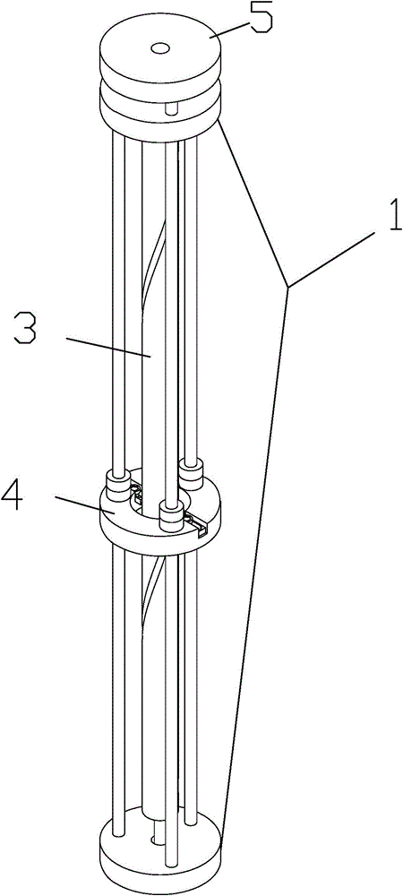
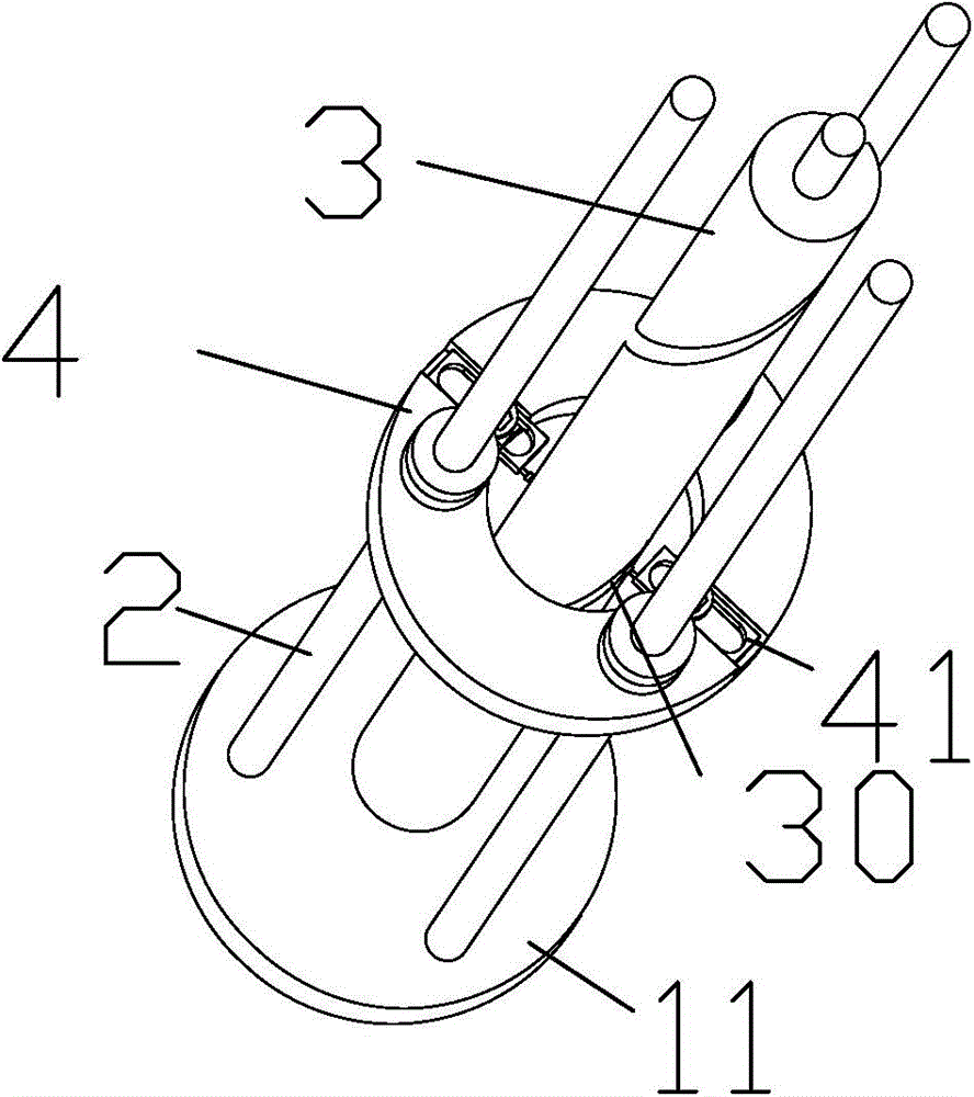
[0027] Please refer to Figure 1 to Figure 3 Shown, show manual screw type kinetic energy production device of the present invention, comprise following element:

[0028] A body 1 is divided into an upper seat 10 and a lower seat 11 . A through hole 100 is defined in the middle of the upper seat 10 . A concave hole 110 is disposed in the middle of the lower seat 11 .

[0029] At least two guide rods 2, preferably three guide rods 2, are fixedly connected between the upper base 10 and the lower base 11, forming a triangle shape.

[0030] A screw 3 is located between the at least three guide rods 2 . The upper end of the screw rod 3 is rotatably connected with the upper base 10 and extends out of the thr...


PUM


Abstract

A manual-operated screw type kinetic energy generation device comprises a seat, a screw, an annular driving disc and a flywheel, wherein the seat is divided into an upper seat and a lower seat; a through hole is formed in the middle of the upper seat; a concave hole is formed in the middle of the lower seat; at least three guide rods are fixedly connected between the upper seat and the lower seat; the screw is located among the at least three guide rods; the upper end of the screw extends out of the through hole in the upper seat; the lower end of the screw is rotationally fixed in the concave hole in the lower seat; threads are formed in the body of the screw; a plurality of via holes are formed in the annular driving disc, and the guide rods penetrate through the via holes; the annular driving disc is hollow, and the screw penetrates through the hollow part of the annular driving disc; two driving jaws are formed on the inner side of the annular driving disc; the two driving jaws go deep into the threads of the screw; the flywheel is meshed with the upper end of the screw and located above the upper seat. The manual-operated screw type kinetic energy generation device is simple in structure, low in cost, capable of regenerating energy and beneficial to environmental development.

Description

technical field [0001] The invention relates to a kinetic energy generating device, in particular to a manual screw type kinetic energy generating device. Background technique [0002] At present, most energy types are restricted by development. For example, petrochemical energy is limited by reserves, is becoming increasingly depleted, and its price is rising steadily. The burning process of petrochemical energy will produce greenhouse gases such as carbon dioxide, which will aggravate the greenhouse effect of the earth itself. In the long run, it is not conducive to the development of environmental protection. Although nuclear energy is cheap, the development of nuclear energy is still quite limited because human beings still have many doubts about whether nuclear power plants can operate well. Other energy sources, such as wind power and solar energy, are too expensive and require space for erection, so they are still not popularized. [0003] At present, there is a tre...

Claims


Application Information

Patent Timeline
Patent Type & Authority Applications(China)
IPC IPC(8): F03G5/06
CPCF03G5/06
Inventor 林世轩
Owner 林世轩
Why Eureka
Eureka Blog
Learn More