
Air conditioning device

An air conditioning, air technology, applied in air conditioning system, control input involving air characteristics, space heating and ventilation, etc., to ensure comfort and maintain the effect of dehumidification

Pending Publication Date: 2015-08-26
DAIKIN IND LTD
View PDF7 Cites 6 Cited by
  • Summary
  • Abstract
  • Description
  • Claims
  • Application Information

AI Technical Summary

Problems solved by technology

Indoor fans are used to generate air flow

Method used


Image

  • Air conditioning device
  • Air conditioning device
  • Air conditioning device

Examples


Embodiment Construction

[0031] (1) The overall structure of the air conditioning device

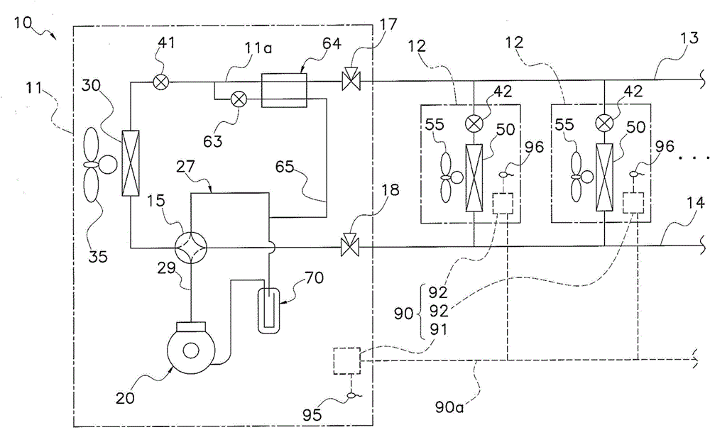
[0032] figure 1 It is a schematic diagram of the refrigerant piping system of the air-conditioning device 10 according to an embodiment of the present invention. The air conditioner 10 is an air conditioner of a distributed refrigerant piping system, and heats or cools each room in a building by performing a vapor compression cooling cycle operation. The air conditioner 10 includes an outdoor unit 11 , a plurality of indoor units 12 , a liquid refrigerant communication pipe 13 and a gas refrigerant communication pipe 14 connecting the outdoor unit 11 and the indoor units 12 . which is, figure 1 The refrigerant circuit of the shown air-conditioning apparatus 10 is constituted by connecting an outdoor unit 11 , an indoor unit 12 , and refrigerant communication pipes 13 and 14 . and, figure 1 The shown refrigerant circuit is loaded with refrigerant, and operates as a cooling cycle in which the refrigerant is co...


PUM


Abstract

The invention provides an air conditioning device which can keep a dehumidification function when the outdoor temperature is low and can guarantee comfort of indoor people. The air conditioning device (10) comprises indoor heat exchangers (50), indoor fans (55), indoor temperature sensors (96), outdoor temperature sensors (95) and indoor control parts (92). During refrigerating operation of the indoor control parts (92) in an automatic mode, a target refrigerating temperature of a target indoor temperature is changed together with the outdoor temperature.

Description

technical field [0001] The invention relates to an air conditioning device. Background technique [0002] Conventionally, an air conditioner is used to perform a cooling operation to perform a dehumidification function. In this cooling operation, the indoor heat exchanger in the air conditioner functions as an evaporator, and the evaporating temperature is set to a temperature lower than the dew point of the indoor air to perform dehumidification that removes moisture contained in the indoor air. effect. [0003] However, when the cooling operation is performed so that the indoor heat exchanger acts as an evaporator to dehumidify, the indoor temperature gradually decreases. When the room temperature drops below the target temperature, the compressor stops running and is in a thermo-off state. Normally, the cooling target temperature when operating in automatic mode is fixed at 28°C. If the cooling operation is performed on a day with high humidity and low air temperature ...

Claims


Application Information

Patent Timeline
IPC IPC(8): F24F3/14F24F11/00
CPCF24F3/14F24F2003/144F24F11/30F24F11/62F24F11/65F24F2110/00F24F2110/20
Inventor 冈本敦
Owner DAIKIN IND LTD
Features
  • Generate Ideas
  • Intellectual Property
  • Life Sciences
  • Materials
  • Tech Scout
  • Unparalleled Data Quality
  • Higher Quality Content
  • 60% Fewer Hallucinations
Learn More