

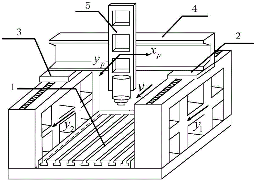
Statistical model-based moving beam type gantry type machine tool dual-drive feed error compensation method and model
A gantry machine tool and dual-drive feeding technology, which is applied in the field of error compensation, can solve problems such as the difficulty in establishing an error compensation table accurately, the inability to characterize the main factors of synchronization errors, and the locking of two axes with dual drives
- Summary
- Abstract
- Description
- Claims
- Application Information
AI Technical Summary
Problems solved by technology
Method used
Image

Examples
Embodiment Construction
[0035] The implementation method of the present invention will be further described in detail below in conjunction with the drawings and embodiments.
[0036] The present invention is based on a statistical model-based dual-drive feed error compensation method for a moving beam type gantry machine tool, comprising the following steps:
[0037]Step 1: For the moving beam gantry machine tool to be compensated, take the input command speed, the different positions of the spindle on the beam, and the different positions of the beam on the double drive shafts, and design an orthogonal experiment to analyze the impact of each factor on For the influence of non-synchronization error, the regression equation of biaxial non-synchronization error and three factors is fitted by multiple linear regression method, and the influence law of each factor is found out.
[0038] The formula of its mathematical model is as follows:
[0039] y ...
PUM
 Abstract
Description
Claims
Application Information