

Electromagnetic law exploration experimental apparatus and experimental method thereof
An experimental method and technology of experimental apparatus, which can be applied in the direction of instruments, educational appliances, teaching models, etc., and can solve the problems of waste of resources, inconvenient use, transportation and storage, etc.
- Summary
- Abstract
- Description
- Claims
- Application Information
AI Technical Summary
Problems solved by technology
Method used
Image

Examples
Embodiment 1
[0117] Embodiment 1 Explore the generation conditions of induced current: imitate Faraday's experiment.
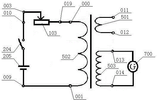
[0118] "Mimicking Faraday's experiment" circuits such as figure 2 shown. The experimental steps are as follows:
[0119] In the first step, the power supply 205 is a No. 5 dry battery, and the terminal ten 010 is connected with the terminal three 003 by a wire, the terminal nineteen 019 is connected with the terminal zero 000, and the terminal one 001 is connected with the terminal nine 009;
[0120] In the second step, connect terminal 13 013 and terminal 14 014 with the positive and negative terminals of the ammeter 700 respectively with wires, turn the selection knob of the ammeter 700 to the 10mA position, and turn the zero adjustment knob to align the pointer with the scale the middle zero point on the plate;
[0121] At this time, the effective circuit is: power supply 205, switch 2 204, potentiometer 1 103, coil 2 502 form a series circuit, coil 3 503 and ammete...
Embodiment 2
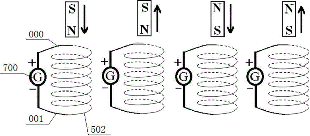
[0130] Embodiment 2 Explore the method of determining the direction of the induced current.
[0131] image 3 It is a schematic diagram of the experimental circuit and operation method. The NdFeB strong magnet has a diameter of 1.2cm and a thickness of 1.5cm, and is installed in a transparent cylinder (the base of the cylinder is thicker, and the magnet can be lifted by hand when it is sucked by the transformer 500). The terminal zero 000 and terminal one 001 at both ends of the 506T coil two 502 are respectively connected to the + and - terminals of the ammeter 700. The range of the ammeter 700 is selected to be 300μA, and the test contact method is used in advance to confirm that when the current flows from the + terminal into the ammeter 700, The pointer deflects to the right. Move the magnet close to or away from the transformer (coil) according to the 4 situations in the figure, and observe the deflection direction of the ammeter 700 pointer.
[0132] Prompt for explora...
Embodiment 3
[0134] Example 3 Explore the influence of the change speed of magnetic flux on the magnitude of the induced current
[0135] The experimental circuit and operation method are also as image 3 As shown, but in each case, when moving the magnet, one should move quickly and the other slowly. During the movement, pay attention to the maximum deflection angle of the ammeter 700 pointer.
[0136] Prompt for exploration: Note the maximum deflection angle of the ammeter 700 needle when comparing "fast movement" with "slow movement".
[0137] Exploration purpose: To find out that the faster the magnetic flux passing through the closed circuit changes, the greater the induced electromotive force and the greater the induced current in the loop (the resistance of the loop remains constant), so as to lay the experimental foundation for understanding Faraday's law of electromagnetic induction.
[0138] Series 2 A series of exploratory experiments on self-induction phenomena
PUM
| Property | Measurement | Unit |
|---|---|---|
| Resistance | aaaaa | aaaaa |
| Diameter | aaaaa | aaaaa |
| Thickness | aaaaa | aaaaa |
Abstract
Description
Claims
Application Information