Method of realizing wound-rotor motor redundant rotation speed feedback and device

A winding motor, speed feedback technology, applied in the direction of AC motor control, electrical components, control systems, etc., can solve the problems of easy interference, rotor frequency drop, slow encoder feedback response, etc., to achieve safe operation, reliable and high application. Requirements and the effect of good safety protection

Active Publication Date: 2015-08-26
SHANGHAI EECTRL ELECTRIC
View PDF7 Cites 4 Cited by
  • Summary
  • Abstract
  • Description
  • Claims
  • Application Information

AI Technical Summary

Problems solved by technology

Because: (1) When using a tachogenerator, there will be disadvantages of residual voltage and phase error, and the size and nature of the load will affect the amplitude and phase of the output voltage; (2) When using rotor frequency feedback, when the winding motor When the torque and the speed are in the same direction, the speed of the wound motor is inversely proportional to the rotor frequency, that is, as the speed of the wound motor increases, the rotor frequency decreases, resulting in a slower feedback response, so that the wound motor cannot be fed back in time. Rotating speed
Therefore, when the torque of the wound motor is in the same direction as the rotational speed, when the wound motor is running at high speed, the rotor frequency feedback cannot detect and feed back the abnormal situation of the wound motor speed in time; (3) When the encoder feedback is used, when When the winding motor is running at low speed, the feedback response of the encoder is slow, resulting in the abnormal situation of the speed of the winding motor cannot be fed back in time; and the feedback signal of the encoder is a weak current signal, which is easily disturbed
Therefore, there are certain defects in the above three speed feedback methods, which are not conducive to obtaining the speed regulation performance of the winding motor and the safe operation of the winding motor

Method used


Image

  • Method of realizing wound-rotor motor redundant rotation speed feedback and device
  • Method of realizing wound-rotor motor redundant rotation speed feedback and device
  • Method of realizing wound-rotor motor redundant rotation speed feedback and device

Examples


Embodiment approach

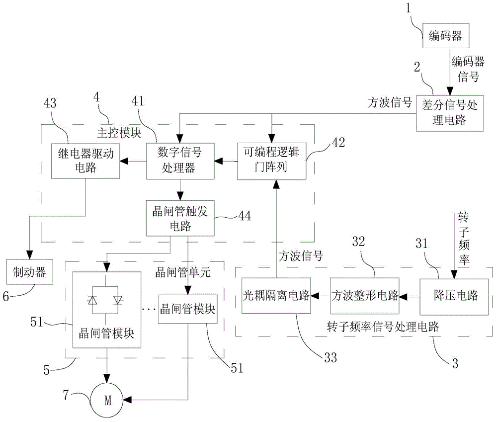
[0067] The rotor frequency signal processing circuit 3 includes a step-down circuit 31, a square wave shaping circuit 32 and an optocoupler isolation circuit 33, the signal input end of the step-down circuit 31 is connected to the signal output end of the rotor winding, and the step-down circuit 31 is connected to the signal output end of the rotor winding. The signal output end of circuit 31 is connected with the signal input end of described square wave shaping circuit 32, and the signal output end of described square wave shaping circuit 32 is connected with the signal input end of described optocoupler isolation circuit 33;

[0068] The main control module 4 includes a digital signal processor 41, a programmable logic gate array 42, a relay drive circuit 43 and a thyristor trigger circuit 44, and the input terminals of the digital signal processor 41 and the programmable logic gate array 42 are all connected to the The output end of the differential signal processing circui...


PUM


Abstract

The invention discloses a method of realizing wound-rotor motor redundant rotation speed feedback and a device. The method comprises steps: according to the quantity of rotary shaft square wave signals within a unit time and the cycle of the rotary shaft square wave signals, a first real-time rotation speed is calculated; according to the cycle of rotor square wave signals, a second real-time rotation speed is calculated; whether the difference value between the first real-time rotation speed and the second real-time rotation speed is in a set range is judged; if not, whether the difference value duration time exceeds the set time is further judged; and if not, abnormal protection signals are sent. The device comprises an encoder, a differential signal processing circuit, a rotor frequency signal processing circuit, a main control module and a thyristor unit. The real-time rotation speed of the wound-rotor motor whether in a high-speed operation condition or in a low-speed operation condition can be timely and accurately fed back, the speed regulation mechanism of the wound-rotor motor can be safely protected, and a reliable guarantee is provided for safety operation of the wound-rotor motor.

Description

technical field [0001] The invention relates to a method and a device for realizing redundant speed feedback of a winding motor, and belongs to the technical field of motor speed control. Background technique [0002] Winding motors are widely used due to their simple structure, convenient use, reliable operation, high efficiency, easy manufacture and low cost. In order to obtain the speed regulation performance of the wound motor, the stator voltage regulation and speed regulation method with the speed feedback function is usually used. Currently, there are three speed feedback methods: tachogenerator, rotor frequency feedback and encoder feedback. Because: (1) When using a tachogenerator, there will be disadvantages of residual voltage and phase error, and the size and nature of the load will affect the amplitude and phase of the output voltage; (2) When using rotor frequency feedback, when the winding motor When the torque and the speed are in the same direction, the sp...

Claims


Application Information

Patent Timeline
Patent Type & Authority Applications(China)
IPC IPC(8): H02P23/00
Inventor 王照岳王照海
Owner SHANGHAI EECTRL ELECTRIC
Why Eureka
Try Eureka