Pressure device and method for thin-walled powder metallurgy shaft sleeve

A technology of powder metallurgy and shaft sleeves, which is applied in the field of manufacturing equipment for thin-walled powder metallurgy shaft sleeves, can solve the problems of increased manufacturing costs, difficulty in ensuring quality, waste of raw materials, etc., achieve high production efficiency, improve lubricity, and reduce labor intensity Effect

Inactive Publication Date: 2015-09-02
ZHEJIANG SF OILLESS BEARING
View PDF9 Cites 4 Cited by
  • Summary
  • Abstract
  • Description
  • Claims
  • Application Information

AI Technical Summary

Problems solved by technology

At present, when some powder metallurgy products of shaft sleeves with very thin wall thickness are made, they are first pressed into bushes with thicker wall thickness (thickened during pressing). After the sintering process is completed, the wall thickness is reduced by metal cutting. Re-processing to thin, this method is more troublesome, and wastes raw materials, increases manufacturing costs, and because the wall thickness is too thin, it is easy to deform during processing and clamping, and the quality is difficult to guarantee

Method used


Image

  • Pressure device and method for thin-walled powder metallurgy shaft sleeve
  • Pressure device and method for thin-walled powder metallurgy shaft sleeve
  • Pressure device and method for thin-walled powder metallurgy shaft sleeve

Examples


Embodiment Construction

[0019] The present invention will be further described below in conjunction with the accompanying drawings.

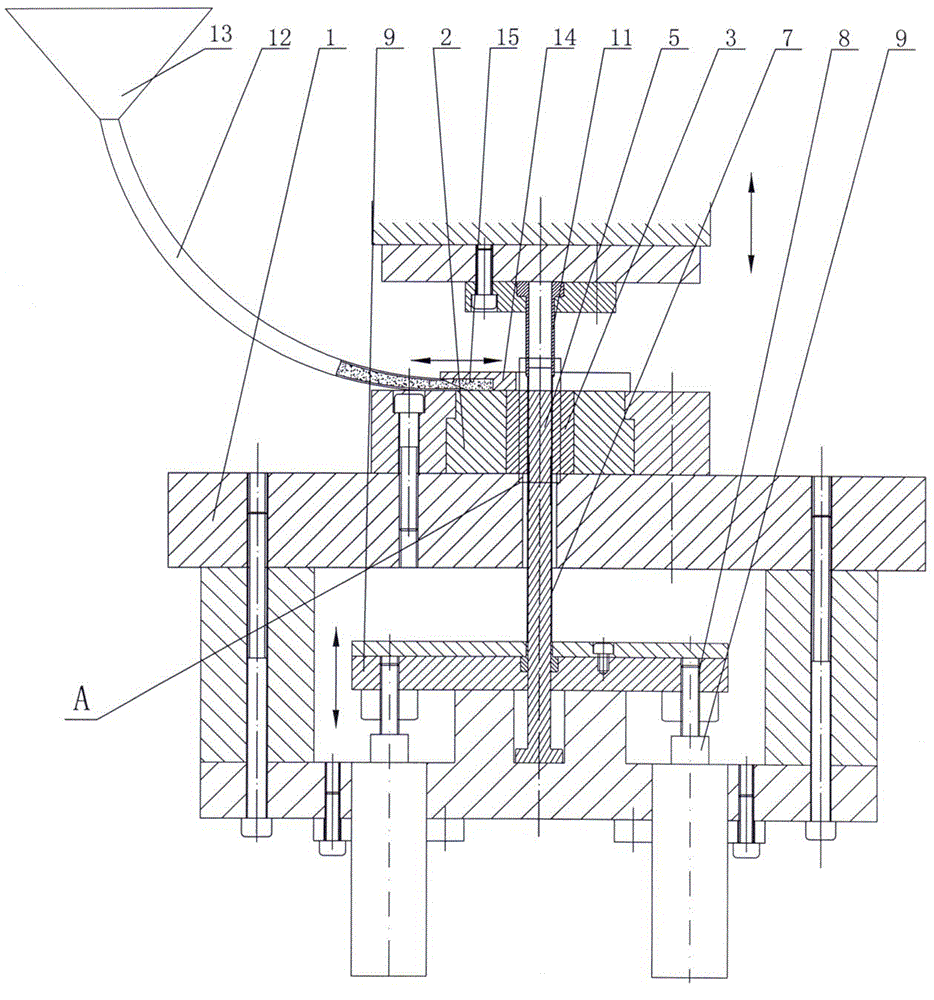
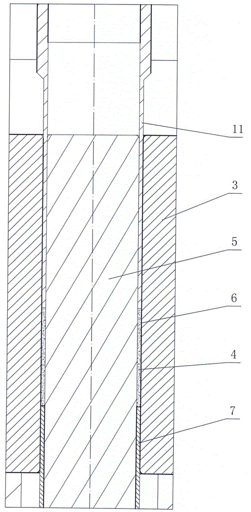
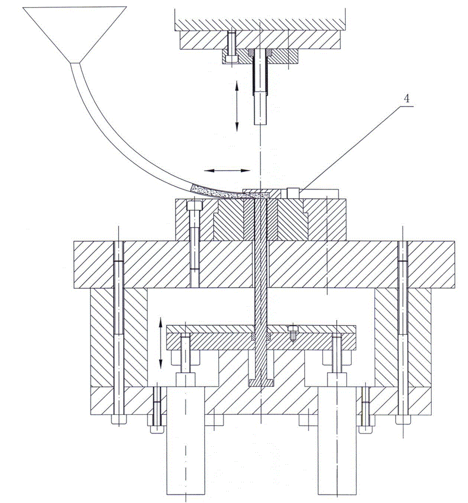
[0020] figure 1 , figure 2 It is a schematic diagram of a pressing device and method for a thin-walled powder metallurgy bushing. As can be seen from the figure, it includes a template 1, a lower mold 2 is fixed on the template 1, a pressing mold 3 made of tungsten steel material is fixed in the lower mold 2, and the inner hole of the pressing mold 3 and the powder metallurgy bushing 4 are fixed. The outer circle is the same. A mandrel 5 is installed in the center of the pressing die 3, the outer circle of the mandrel 5 is the same as the inner hole of the powder metallurgy bushing 4, and the inner hole of the pressing die 3 and the outer circle of the mandrel 5 form a circle for pressing the powder metallurgy bushing 4 Annular mold cavity 6, on the outer circle of mandrel 5, there is an ejector sleeve 7 for pushing out powder metallurgy sleeve 4, the height of pow...


PUM


Abstract

The invention provides a pressure device and method for a thin-walled powder metallurgy shaft sleeve. The device comprises a template, wherein a lower die is fixed on the template. The device is characterized in that a pressing die is fixed in the lower die; an inner hole in the pressing die is the same as the excircle of the powder metallurgy shaft sleeve; a core rod is mounted in the center of the pressing die; the excircle of the core rod is the same as an inner hole in the powder metallurgy shaft sleeve; the inner hole in the pressing die and the excircle of the core rod are combined to form a die cavity for pressing of the powder metallurgy shaft sleeve; an ejecting sleeve for pushing out the powder metallurgy shaft sleeve is arranged on the excircle of the core rod; the lower end of the ejecting sleeve is connected with an ejecting device capable of moving up and down; an upper punch connected with a punch press sliding block is arranged above the die cavity; the front end of the upper punch takes the shape of a circular tube matched with the die cavity; a powder feeding pipe for a power metallurgy material is arranged above the die cavity, and can move left and right; a material pushing plate is connected with the front end of the powder feeding pipe; when the powder feeding pipe moves to the die cavity, the material pushing plate pushes the powder metallurgy shaft sleeve to move out of a punching area; a graphite powder material is added into the power metallurgy material, and the weight of the added graphite powder material accounts for 1-2% of the total weight.

Description

technical field [0001] The invention relates to the manufacture of powder metallurgy shaft sleeve parts, in particular to the manufacturing equipment and method of thin-walled powder metallurgy shaft sleeves. Background technique [0002] Most of the products made of powder metallurgy bushing parts that we routinely make have a wall thickness of more than 1 mm. Powder metallurgy bushing products with a wall thickness of less than 1 mm are difficult to produce, or even impossible. At present, when some powder metallurgy products of shaft sleeves with very thin wall thickness are made, they are first pressed into bushes with thicker wall thickness (thickened during pressing). After the sintering process is completed, the wall thickness is reduced by metal cutting. It is troublesome to process it until it is thinner, and it wastes raw materials and increases manufacturing costs. Moreover, because the wall thickness is too thin, it is easy to deform during clamping and other pr...

Claims


Application Information

Patent Timeline
Patent Type & Authority Applications(China)
IPC IPC(8): B22F3/03B22F5/10
Inventor 沈之明崔泉源
Owner ZHEJIANG SF OILLESS BEARING
Why Eureka
Try Eureka