
An aircraft wing with an aerodynamic layout and an aircraft using the same

A wing and aircraft technology, applied in the field of aircraft wings, can solve the problems of large overall resistance and small effective wingspan of the joint wing layout, and achieve the effect of reducing induced resistance and good stability

Active Publication Date: 2017-03-01
万绍明
View PDF1 Cites 0 Cited by
  • Summary
  • Abstract
  • Description
  • Claims
  • Application Information

AI Technical Summary

Problems solved by technology

[0006] The present invention provides an aircraft wing to solve the technical problem that the effective wingspan of the joint-wing layout is relatively small due to the large overall resistance of the aerodynamic layout of the joint-wing aircraft in the prior art; at the same time, the present invention also provides a wing of airplane

Method used


Image

  • An aircraft wing with an aerodynamic layout and an aircraft using the same
  • An aircraft wing with an aerodynamic layout and an aircraft using the same
  • An aircraft wing with an aerodynamic layout and an aircraft using the same

Examples


Embodiment 2

[0047] Such as Figure 10 to Figure 12 As shown, the present embodiment provides a kind of aircraft wing, and the main difference between this aircraft wing and the embodiment of above-mentioned aircraft is the wing shape of the wing, the first upper plane of the united wing in the present embodiment The wing section 21 and the first lower wing section 31 are all trapezoidal wings whose chord length is greater than the chord length of the wingtip. Although the first upper wing section 21 also runs through the wing section here, the first upper The wing root 210 of the wing section 21 is located through the middle of the wing section. At this time, the chord of the combined wing tip section formed by the dislocation and serial connection of the outer ends of the upper and lower wing sections is less than the difference between the wing root chord length of the upper wing section and the wing root chord length of the lower wing section. And, the joint wing structure of this str...

Embodiment 3

[0049] Such as Figure 13 to Figure 15 As shown, the present embodiment provides a kind of aircraft wing, and the main difference between this aircraft wing and the embodiment of above-mentioned aircraft is the wing shape of the wing, the second upper plane of the united wing in the present embodiment Wing section 22, the second lower wing section 32 all are the trapezoidal wing that the chord length of wing root is less than the chord length of wingtip, although the second upper wing section 22 is also the through wing section here, the second upper machine The wing root 220 of the wing section 22 is located in the middle of the through wing section. At this time, the chord of the combined wingtip section formed by the dislocation and series connection of the outer ends of the upper and lower wing sections is greater than the difference between the root chord length of the upper wing section and the root chord length of the lower wing section. And, the joint-wing structure o...


PUM


Abstract

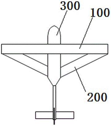
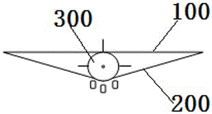
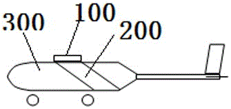
The invention provides an aircraft wing with a novel aerodynamic layout and an aircraft using the same. The aircraft comprises a fuselage, and an upper wing section and a lower wing section which are fixedly connected with the fuselage and outwardly extend along spanwise respectively, a wingtip of the upper wing section and the wingtip of the lower wing section are serially and fixedly connected along the spanwise in a staggered manner to form a combined wingtip section so that the upper wing section, the lower wing section and the fuselage form a ditrigon structure, the spanwise is defined as a back-forth direction, the trailing edge of the wingtip at the front side is connected with a leading edge of the wingtip at the rear side. According to the modern close coupling principle, the wingtip at the leading edge can disturb the airflow born by the tailing wingtip, the resistance influence caused by the airflow disturbance to the rear wingtip is lowered, the wingtip vortex produced by the front wingtip is continuously digested by the rear wingtip, the wingtip vortex produced by the front wingtip has lifting force effect on the rear wingtip, and then the effective wingspan for producing the lifting force effect of the combined wing in the triangle structure is enhanced.

Description

technical field [0001] The invention relates to an aircraft wing with a novel aerodynamic layout and an aircraft using the wing. Background technique [0002] Light or ultra-light aircraft are not only "friendly to the people", but also have a wide range of applications. Because the cost of this type of aircraft is relatively low, the production is relatively easy, and the development cycle is short, so this type of small aircraft has rich aerodynamic shape, exquisite structural design, and more novel technical manifestations than large aircraft. [0003] In order to obtain a larger lift-to-drag ratio, light aircraft usually adopt a wing structure with a large aspect ratio, and the wing area is usually large so that the span of a single wing is large. However, the mechanical strength structure of such an overly slender wing has low efficiency, which is not conducive to transmitting the lift of the wing to the fuselage, and this thin and large-aspect-ratio wing must have hig...

Claims


Application Information

Patent Timeline
Patent Type & Authority Patents(China)
IPC IPC(8): B64C3/10B64C3/36
Inventor 万绍明张镭刘鹏飞牛谦
Owner 万绍明
Learn More