Automatic clothes drying rack with reduction gears

A technology of deceleration device and clothes hanger, which is applied in the field of clothes hangers, can solve problems such as safety accidents, wear and tear of lifting ropes, failure of clothes hanger control, etc., and achieve the effect of avoiding safety accidents and reducing potential safety hazards

Active Publication Date: 2015-09-02
九牧智能厨卫(安徽)有限公司
5 Cites 1 Cited by

AI-Extracted Technical Summary

Problems solved by technology

[0003] During the use of the drying rack, the control failure may occur, especially if the control failure occurs during the rising process of the drying rod, when the telescopic bracket is folded to the uppermost end and cannot be folded again, and the motor is still working, it will The lifting rope i...

Method used

Referring to Fig. 5, the automatic clothes hanger of the present invention, its difference with embodiment 1 is: transmission member 520 also comprises planetary carrier 526 and 3 planetary gears 528, and 3 planetary gears 528 are socketed on planetary carrier 526- side and meshes with the gear 524 on the reduction wheel 510, wherein the gear 524 is used as the sun gear. The other side of the planet carrier 526 is also fixed with a gear 526 a meshing with the rack 522 . A mounting hole is provided in the middle of the planet ...

Abstract

The invention discloses an automatic clothes drying rack with reduction gears. The automatic clothes drying rack comprises at least one reduction gear. Each reduction gear comprises a reduction wheel, a transmission part, a limit part and at least one brake. The reduction wheels are arranged on a pin shaft of a lifting bracket, the brakes are arranged on the surface of the reduction wheels, the limit parts are arranged on the outer portions of the reduction wheels and the brakes, and the transmission parts are arranged between the reduction wheels and a support and drive the reduction wheels and the brakes to rotate relative to the limit parts when sliding on the pin shaft until the brakes deviate from the reduction wheels under the action of centrifuge and contact with the limit parts, the limit parts limit rotation of the brakes to brake the reduction wheels. The automatic clothes drying rack can prevent safety problems caused by breakage of lifting ropes and quick falling of drying rods of the drying rack.

Application Domain

Other drying apparatusTextiles and paper

Technology Topic

EngineeringMechanical engineering +1

Image

  • Automatic clothes drying rack with reduction gears
  • Automatic clothes drying rack with reduction gears
  • Automatic clothes drying rack with reduction gears

Examples

  • Experimental program(2)

Example Embodiment

[0024] Example 1
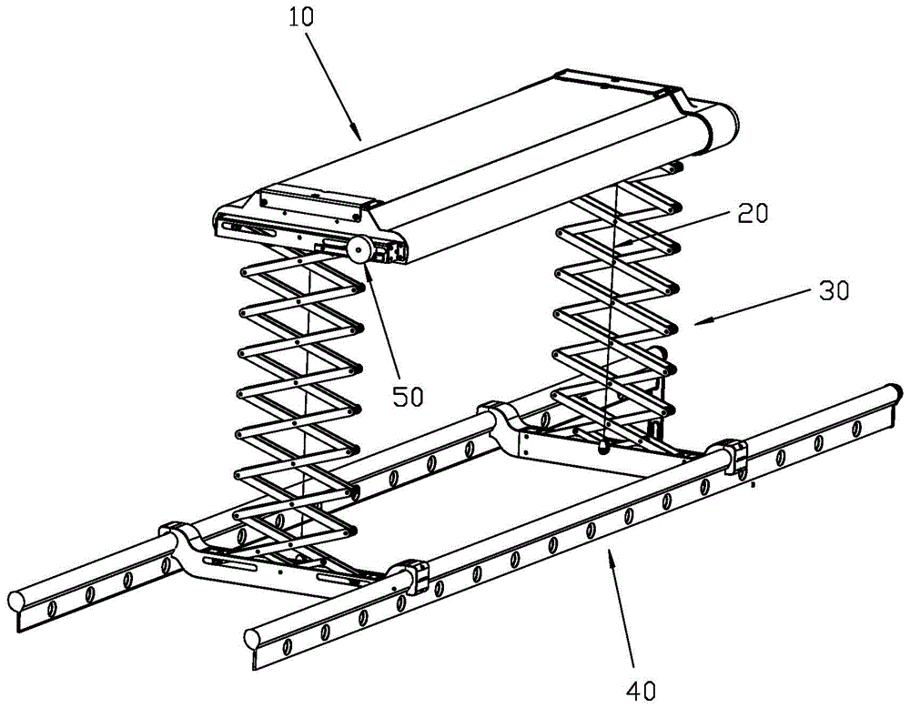
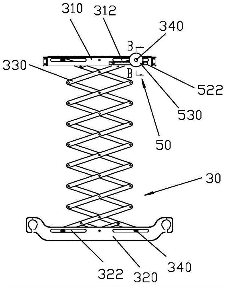
[0025] Such as Figure 1-4 As shown, the automatic drying rack of the present invention includes a body 10, a lifting rope 20, a lifting bracket 30, a drying rod 40, a speed reduction device 50, and the like. The lifting bracket 30 has an upper bracket 310 fixed to the body 10, a lower bracket 320 fixed to the drying rod 40, and a folding rod 330 located between the two. The upper bracket 310 is provided with a sliding groove 312, the upper end of the folding rod 330 is connected with a pin shaft 340, the pin shaft 340 is inserted into the sliding groove 312 and sliding in the sliding groove 312 as the folding rod 330 is unfolded and folded.
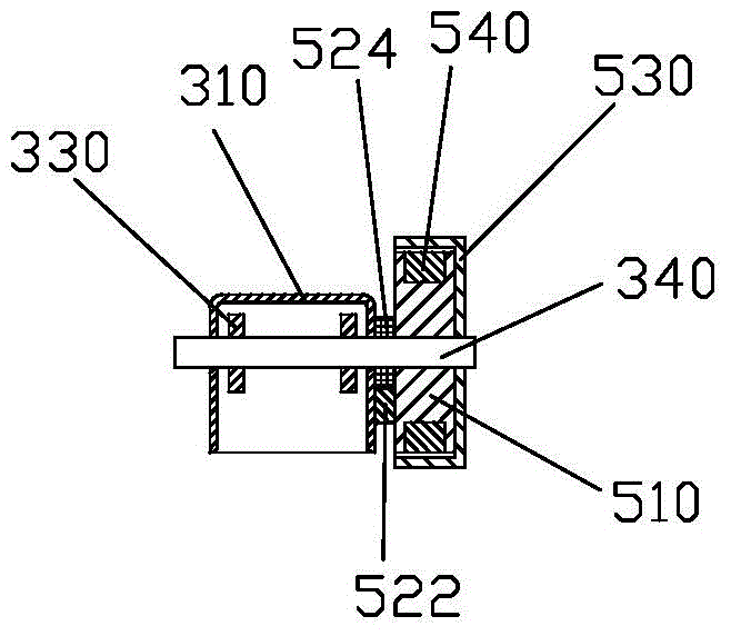
[0026] The deceleration device 50 is disposed on the pin shaft 340 and includes a deceleration wheel 510, a transmission member 520, a restriction member 530 and a brake block 540. The reduction wheel 510 is a cylinder and includes an outer circumferential surface and two side surfaces. Two semicircular annular grooves 512 are provided on the outer circumferential surface, and a baffle 514 is formed between the grooves. The brake blocks 540 are two semi-circular friction blocks that fit the shape of the groove 512 and are respectively placed in the groove 512. The limiting member 530 has a circular inner cavity 532 with one side open, and is sleeved on the reduction wheel 510 and the brake block 540. The assembled reduction wheel 510 and the restricting member 530 can be sleeved on the pin shaft 340 through the central mounting hole, wherein the opening of the inner cavity 532 faces the sliding groove 312, and the edge of the opening is symmetrically provided with two bosses 534, and the bosses 534 are inserted In the chute 312. The distance between the inner cavity 532 of the limiting member and the outer circumferential surface of the reduction wheel 510 is less than the thickness of the brake block 540, that is, the movable range of the brake block 540 is limited by the baffle 514 and the limiting member 530 and cannot be completely separated Slot 512.
[0027] The transmission member 520 includes a rack 522 and a gear 524. The rack 522 is fixed on the bracket 310 in parallel along the sliding groove 312, and the teeth face the sliding groove 312. The gear 524 has a mounting hole, which is sleeved on the pin shaft 340 and fixed on one side of the reduction wheel 510, and the rack 522 and the teeth of the gear 524 mesh.
[0028] When working, the winding of the lifting rope 20 drives the folding or unfolding of the lifting bracket 30, and the pin 340 slides in the sliding groove 312 accordingly, driving the reduction wheel 510, the limiting member 530 and the brake between the reduction gear 50 The block 540 moves along the chute 312. The reduction wheel 510 moves in parallel and rotates with the pin shaft 340 as an axis under the meshing action of the gear 524 and the rack 522. Since the boss 534 is inserted into the sliding groove 312, the restricting member 530 only moves in parallel without rotating. During normal operation, the moving speed of the lifting bracket 30 is relatively slow, and the speed of the reduction wheel 510 is also relatively slow. The brake block 540 rotates synchronously with the reduction wheel 510 in the groove 512, and does not affect the lifting of the drying rod 40. When a fault causes the lifting bracket 30 to move quickly, for example, when the lifting rope 20 is broken and the lifting bracket 30 is rapidly deployed, the speed reduction wheel 510 will be driven to rotate rapidly, and the brake block 540 will also rotate rapidly and deviate outward under the action of centrifugal force. The deceleration wheel 510 is in contact with the limiting member 530. Due to the friction between the rotating brake block 540 and the non-rotating limiting member 530, the rotational speed of the brake block 540 is lower than that of the reduction wheel 510 and is blocked by the baffle 514. The rotation of the reduction wheel 510 further hinders the sliding speed of the pin shaft 340 in the sliding groove 312, thereby slowing down the unfolding speed of the lifting bracket 30 and achieving the purpose of slowing down the descending speed of the drying rod 40.

Example Embodiment

[0029] Example 2
[0030] See Figure 5 The difference between the automatic drying rack of the present invention and the first embodiment is that the transmission member 520 also includes a planet carrier 526 and three planetary gears 528. The three planetary gears 528 are sleeved on one side of the planet carrier 526 and connected with the reduction gear 510. The upper gear 524 meshes with the gear 524 acting as a sun gear. A gear 526a meshed with the rack 522 is also fixed on the other side of the planet carrier 526. The planet carrier 526 is provided with a mounting hole in the middle, and is sleeved on the pin shaft 340. The cavity wall at the edge of the opening of the inner cavity of the restricting member 530 is provided with teeth 536 meshing with the planetary gear 528. Through the arrangement of the planetary gear system, the speed of the reduction wheel 510 can be increased, the centrifugal force of the brake block 540 can be enhanced, thereby increasing the friction force in the reduction device 50, when the lifting rope 20 is broken, the lifting bracket 30 can be better controlled Decline.
[0031] For other components and working processes of this embodiment, refer to Embodiment 1, and will not be described again.
[0032] In the above-mentioned embodiment of the present invention, the lower bracket 320 may also have a sliding groove 322 at the same time, and the reduction gear may be separately arranged on the pin 340 of the lower bracket 320, or there may be multiple reduction devices arranged on the upper and lower brackets at the same time. There is no restriction on this.
[0033] In addition to setting the boss to be inserted into the sliding groove, the restricting member of the present invention can also be fixed to a pin shaft, a bracket, etc. to prevent it from rotating synchronously with the reduction wheel, and does not restrict this.

PUM

no PUM

Description & Claims & Application Information

We can also present the details of the Description, Claims and Application information to help users get a comprehensive understanding of the technical details of the patent, such as background art, summary of invention, brief description of drawings, description of embodiments, and other original content. On the other hand, users can also determine the specific scope of protection of the technology through the list of claims; as well as understand the changes in the life cycle of the technology with the presentation of the patent timeline. Login to view more.

Similar technology patents

Adjusting plate self provided with backup protection device

ActiveCN105914650AReduce security risksSave the backup protection measures for laying wires
Owner:JINCHENG POWER SUPPLY COMPANY OF STATE GRID SHANXI ELECTRIC POWER +1

Radius-based video monitoring platform security certification method

ActiveCN106685955Aprevent intrusionReduce security risks
Owner:武汉微创光电股份有限公司

Classification and recommendation of technical efficacy words

  • Reduce security risks
  • avoid safety accidents

Automatic driving system

Owner:CHERY AUTOMOBILE CO LTD

Power safety socket device

ActiveCN106848698AReduce security risksImprove power supply stability
Owner:东莞科奔电器有限公司

Method for optimizing and balancing power-cut schemes

InactiveCN104156790AReduce security risksReduce the number of outages
Owner:STATE GRID CORP OF CHINA +2

Child safety door fence

Owner:浙江鑫博婴童用品有限公司

Hinge device for kraut refrigerator

Owner:TAIZHOU LG ELECTRONICS REFRIGERATOR CO LTD

Guiding lighting system

InactiveCN102378434AAvoid safety accidentsEnsure long-distance vision
Owner:IDSYS
Why Eureka
Try Eureka