Lateral girder erection and construction method for truss double-girder type bridge girder erection machine

A bridge erecting machine and double-girder technology, which is applied in bridge construction, erection/assembly of bridges, bridges, etc., can solve the problems of particularly unfavorable construction cost control, large limitations, and inapplicability, so as to reduce repeated installation and dismantling and The effect of appearance, strong wind resistance, and reduced workload

Active Publication Date: 2015-09-02
CHINA RAILWAY SIXTH GROUP
View PDF5 Cites 22 Cited by
  • Summary
  • Abstract
  • Description
  • Claims
  • Application Information

AI Technical Summary

Problems solved by technology

The site selection of the beam yard is also affected by the construction environment, which has great limitations
The traditional construction method of starting from the bridge and ending at the end of the beam, sequentially feeding the beam, and erecting the bridge machine is not applicable due to the continuous lengthening of the bridge, the limitation of the site selection of the beam yard, and the limitation of the transportation road.
However, use large-tonnage truck cranes or crawler cranes to erect part of the prefabricated girders, and then assemble the bridge erecting machine on the erected girders, and then adopt the scheme of bridge erection frame beams, the entry and exit of equipment in this scheme and the treatment of the construction site for beam erection A large amount of additional cost is required, which is particularly unfavorable to construction cost control; and with the emergence of high piers, higher requirements are also put forward for crane equipment

Method used


Image

  • Lateral girder erection and construction method for truss double-girder type bridge girder erection machine
  • Lateral girder erection and construction method for truss double-girder type bridge girder erection machine
  • Lateral girder erection and construction method for truss double-girder type bridge girder erection machine

Examples


Embodiment Construction

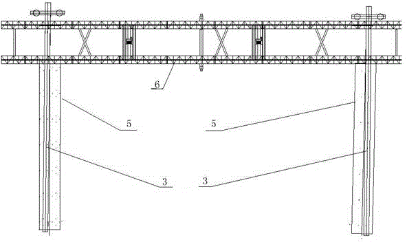
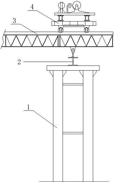
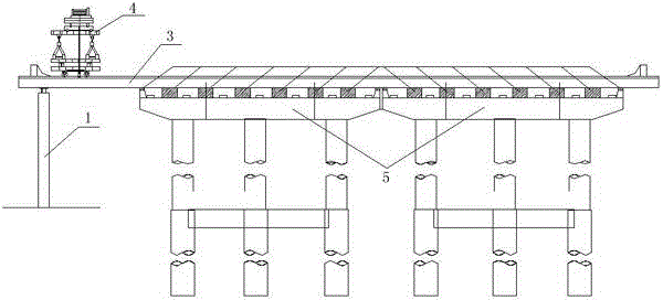
[0039] A side feeding girder erection structure of a truss double girder type bridge erecting machine, including two traverse rails respectively arranged on the top of the cover beam at both ends of the hole to be erected, the two ends of the traverse rail are suspended outside the cover beam, and the externally suspended ends Supported on temporary buttresses, the top of the two traversing tracks is equipped with a high-level gantry crane structure with traversing wheel boxes as the running system.

[0040] The temporary support pier includes a double-supported steel pipe support column arranged on the extension line of the cover beam, a pile cap is installed on the top of the steel pipe support column, and a double I-beam distribution beam is installed on the top of the pile cap.

[0041] The high-level gantry crane structure includes traversing wheel boxes respectively installed on the two traversing rails, the tops of the two traversing wheel boxes are installed with main l...


PUM


Abstract

The invention belongs to a precast girder mounting construction method, in particular to a lateral girder erection and construction method for a truss double-girder type bridge girder erection machine. A lateral girder erection structure of the truss double-girder type bridge girder erection machine comprises two transverse moving tracks, wherein the two transverse moving tracks are respectively arranged on the tops of bent caps at two ends of a to-be-erected hole; two ends of each transverse moving track are suspended out of the bent caps; outer suspended ends of each transverse moving track are supported on temporary buttresses; a high-position gantry crane structure is arranged on the tops of the two transverse moving tracks; and a transverse moving wheel box serves as a walking system of the high-position gantry crane structure. The construction method comprises the following steps of mounting the temporary buttresses; mounting and reinforcing the transverse moving tracks; mounting main longitudinal girders; and assembling, examining and receiving the bridge girder erection machine. The lateral girder erection method of the truss double-girder type bridge girder erection machine comprises the following steps of girder conveying, girder feeding, girder lifting, transverse moving, girder falling, temporary reinforcing and welding of crossbeams among girders. By the lateral girder erection and construction method for the truss double-girder type bridge girder erection machine, the construction cost is reduced effectively, and construction safety is ensured.

Description

technical field [0001] The invention belongs to a prefabricated beam body installation and construction method, in particular to a side beam feeding and erection construction method of a truss double beam type bridge erecting machine. Background technique [0002] With the rapid development of highway and municipal engineering construction in our country, there are more and more highway and municipal bridge projects, the construction period is getting shorter and shorter, and the construction environment is becoming more and more complex. The site selection of the beam yard is also affected by the construction environment, which has great limitations. The traditional construction method of starting from the bridge and ending at the end of the beam erection, feeding the beams sequentially, and erecting the bridge erecting machine is also not suitable due to factors such as the continuous lengthening of the bridge, the limitation of the site selection of the beam yard, and the...

Claims


Application Information

Patent Timeline
Patent Type & Authority Applications(China)
IPC IPC(8): E01D21/00
Inventor 李义堂郝晋新赵志明陈钧张维红贺高强郝腾飞王颖高勇强任浩马俊飞
Owner CHINA RAILWAY SIXTH GROUP
Why Eureka
Try Eureka