Shear strengthening of steel beam ends at beam-to-column joints

A beam-column joint, strengthening structure technology, applied in building construction, building maintenance, construction and other directions, can solve problems such as large thickness, affecting building functions, procurement and welding difficulties, etc., to improve shear bearing capacity, simple construction, The effect of avoiding sourcing and welding challenges

Inactive Publication Date: 2017-02-22
TONGJI UNIV +1
View PDF6 Cites 0 Cited by
  • Summary
  • Abstract
  • Description
  • Claims
  • Application Information

AI Technical Summary

Problems solved by technology

[0005] However, if the height of the section is increased, the heightened steel girder will inevitably affect the realization of the building function; and if the web of the steel girder is thickened, it is often difficult to purchase and weld due to the thickness

Method used


Image

  • Shear strengthening of steel beam ends at beam-to-column joints
  • Shear strengthening of steel beam ends at beam-to-column joints
  • Shear strengthening of steel beam ends at beam-to-column joints

Examples


Embodiment 1

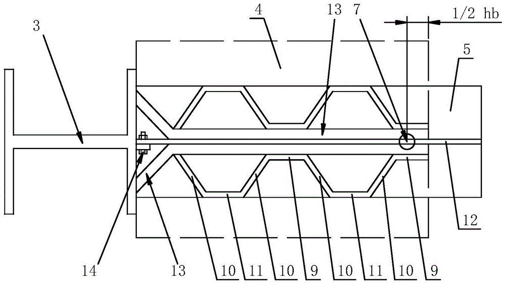
[0052] According to the requirement of shear bearing capacity, the required thickness δ of the corrugated steel plate is more than 20 mm; and the web 12 at the end of the steel beam 1 and the flange of the peripheral column 3 are connected together by bolts 14 .

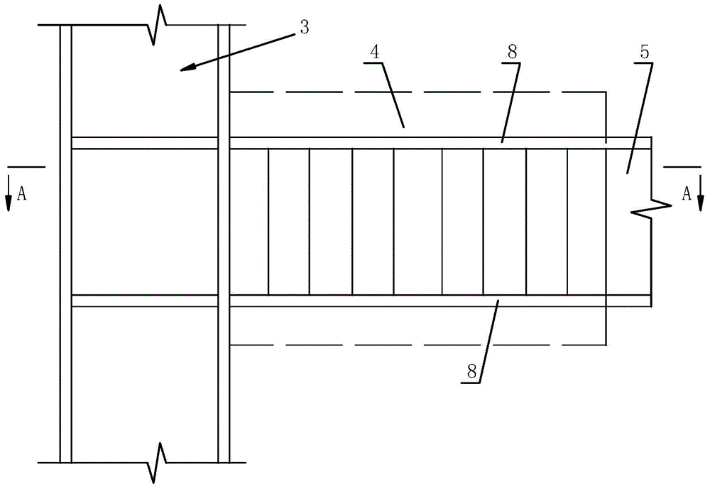
[0053] Then, if figure 2 , image 3 As shown, a flat steel plate 13 is welded closely to both sides of the web 12 of the shear reinforcement section 4 respectively, the thickness of the flat steel plate 13 is 1 / 3δ, and the flat steel plate 13 is provided with an oblique section (not shown in the figure Out), the oblique section of the flat steel plate 13 is between the area where the bolt 14 is located and the end of the steel beam 1, so that the oblique section of the flat steel plate 13 is welded together with the flange of the peripheral column 3; The corrugated steel plate is arranged on the outside of the flat steel plate 13, the actual thickness of the corrugated steel plate is 1 / 6δ (in a word, the actual thi...

Embodiment 2

[0055] According to the requirement of shear bearing capacity, the required thickness δ of the corrugated steel plate is more than 20 mm; and the web 12 at the end of the steel beam 1 and the flange of the peripheral column 3 are connected together by welding.

[0056] Then, if figure 2 , Figure 4 As shown, on both sides of the web 12 of the shear strengthening section 4, a flat steel plate 13 is welded closely to each other, and the thickness of the flat steel plate 13 is 1 / 3δ, so that the flat steel plate 13 and the peripheral column 3 The flanges are welded together, and the corrugated steel plate is arranged on the outside of the flat steel plate 13. The actual thickness of the corrugated steel plate is 1 / 6δ (in a word, the actual thickness of the corrugated steel plate is not greater than 20mm), so that the corrugated steel plate The first horizontal section 9 of the corrugated steel plate is welded close to the flat steel plate 13, so that the end of the steel beam 1 ...

Embodiment 3

[0058] According to the requirement of shear bearing capacity, the required thickness δ of the corrugated steel plate is not greater than 20 mm; and the web 12 at the end of the steel beam 1 and the flange of the peripheral column 3 are connected together by bolts 14 .

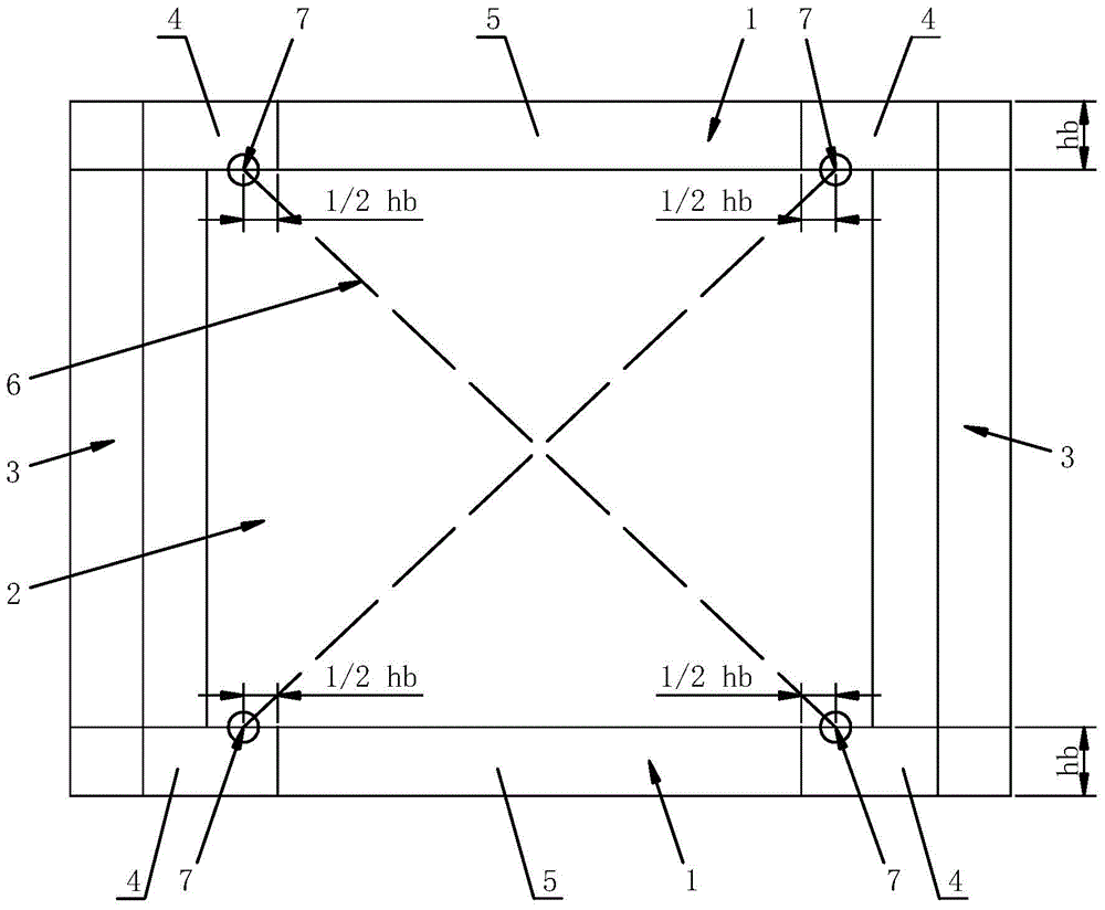
[0059] Then, the actual thickness of the corrugated steel plate is the required thickness δ; figure 2 , Figure 5 As shown, the corrugated steel plate is arranged on both sides of the web 12 of the shear strengthening section 4, and at the point 7 of the vertical resultant force, the first horizontal section 9 of the corrugated steel plate is close to the The web 12 of the steel beam 1 is welded; the area where the bolt 14 is located to the end of the steel beam 1 is the oblique section 10 of the corrugated steel plate, and the oblique section 10 of the corrugated steel plate is connected to the oblique section 10 of the corrugated steel plate. The two flanges 8 of the shear strengthening section 4 are welde...


PUM

PropertyMeasurementUnit
thicknessaaaaaaaaaa

Abstract

The invention provides a shearing-resistance reinforcing structure at the end parts of steel girders at a node of a beam column. The shearing-resistance reinforcing structure comprises a buckling-restrained steel plate wall, steel girders and peripheral columns, wherein the end parts of the steel girders are connected with peripheral columns, an equivalent eccentrically-intercrossed support of the buckling-restrained steel plate wall and the steel girders are intersected at vertical resultant force application points; each steel girder comprises a shearing-resistance reinforcing section and a non-shearing resistance reinforcing section, the height of the steel girder is hb, and the shearing-resistance reinforcing section comprises an area between the end part of each steel girder and the corresponding vertical resultant force application point and an area where the vertical resultant force application point extends outwards for 1 / 2hb; the two sides of a web of the shearing-resistance reinforcing section are provided with corrugated steel plates which comprise first horizontal sections, second horizontal sections and slant sections, and the first horizontal sections are closely welded with the steel girder webs at the vertical resultant force application points; the slant sections are welded with two flange edges of the shearing-resistance reinforcing section, and the corrugated steel plates are welded with the flange edges of the peripheral columns at the end parts of the steel girders. According to the shearing-resistance reinforcing structure provided by the invention, the building function can be beneficially realized; meanwhile, the purchasing and welding difficult problems caused by adopting thicker webs can be prevented.

Description

technical field [0001] The invention relates to the technical field of construction engineering, in particular to a shear reinforcement structure at the end of a steel beam at a beam-column node. Background technique [0002] As a structural energy-dissipating member with excellent performance, the buckling-resistant steel plate wall has very stable hysteretic characteristics and good low-cycle fatigue characteristics, which can greatly improve the lateral stiffness and bearing capacity of the structure, and at the same time provide the structure with plastic energy dissipation. It provides a considerable additional damping ratio, thereby reducing the seismic response of the structure, so it has a wide application prospect. [0003] In order to avoid the adverse effects of additional axial force and additional bending moment on the surrounding columns after the steel plate wall is connected to the surrounding columns, the buckling-resistant steel plate wall is generally conn...

Claims


Application Information

Patent Timeline
Patent Type & Authority Patents(China)
IPC IPC(8): E04G23/02
Inventor 金华建孙飞飞李国强
Owner TONGJI UNIV
Why Eureka
Try Eureka