
Method for driving power generators to generate power under descending actions of lifting deceleration strips rolled by wheels

A technology of lifting drive and deceleration bar, which is applied in the direction of engines, machines/engines, mechanical equipment, etc., to achieve the effect of low pollution, low cost and value creation

Inactive Publication Date: 2015-09-02
康国强
View PDF4 Cites 4 Cited by
  • Summary
  • Abstract
  • Description
  • Claims
  • Application Information

AI Technical Summary

Problems solved by technology

But my invention uses the inertia of the car and self-weight rolling to generate electricity, so it is easier to obtain kinetic energy and implement it

Method used


Image

  • Method for driving power generators to generate power under descending actions of lifting deceleration strips rolled by wheels
  • Method for driving power generators to generate power under descending actions of lifting deceleration strips rolled by wheels
  • Method for driving power generators to generate power under descending actions of lifting deceleration strips rolled by wheels

Examples


example 1

[0005] Example 1: Set up 9 kinetic energy transmission devices of "lifting and decelerating strips" on the lanes of the drop-off area and the pick-up area of ​​the airport or high-speed railway station, respectively drive the same generator separately, and each passenger car continuously rolls 9 Each speed bump uses the inertia and weight of the car to press down on the device to convert the kinetic energy into electrical energy. After storage and inversion, it can be used stably by various electrical equipment in airports or high-speed rail stations.

example 2

[0006] Example 2: A high-power power generation device for rolling "lifting speed bumps" is installed on a road section where there are many buses traveling and the speed limit is required to enter the station. The inertia and weight of the bus frequently roll over the speed bumps, and the kinetic energy generated is converted into Electric energy, after being stored and inverted, can be used stably by the electrical equipment of the roadside bus shelters.

example 3

[0007] Example 3: A rolling high-power power generation device is installed on the rails of a certain subway station where the speed is limited to enter the station. Through the inertia and weight of the subway, multiple wheels of the subway frequently roll over the speed reduction strip, and the kinetic energy generated is converted into electrical energy. After storage and inverter, it can be used stably for the electrical equipment of the subway station.


PUM


Abstract

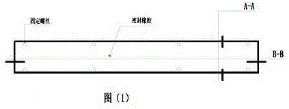
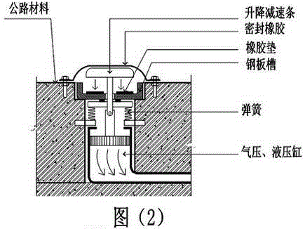
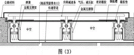
The invention discloses a method for driving power generators to generate power under the descending actions of lifting deceleration strips rolled by wheels. The method has the advantages that kinetic energy generated when the 'lifting deceleration strips' rolled by the wheels is transmitted to certain positions by pneumatic and hydraulic transmitters, the power generators can be conveniently mounted at the certain positions, a plurality of gears can be driven to rotate after the speeds are increased, or various bidirectional rotation and unidirectional rotation output gears on shafts of the power generators can be respectively driven by hydraulic motors to rotate, so that each power generator can rotate towards a direction to generate electric energy; 13-25V varying alternating currents outputted by the power generators only can be used for charging 12V storage batteries to be stored after being rectified by rectifiers due to unstable vehicle flow, and the electric energy generated by the miniature power generators driven by the 'lifting deceleration strips' rolled by the wheels can be converted into chemical energy; the chemical energy in the storage batteries can be converted into alternating-current 220V mains supply by inverter power supplies with protection circuits, and the alternating-current 220V mains supply can be transmitted to diversified electric devices to be stably utilized by the various electric devices.

Description

technical field [0001] The invention utilizes the kinetic energy generated by rolling the "lifting speed reduction bar" of the wheel to drive the coil of the generator to cut and work in the magnetic field to generate electric energy. Background technique [0002] There are more and more cars in modern society, using the kinetic energy generated by the rolling of the wheels of cars and railcars to "lift the speed reduction bar" down, through mature pneumatic or hydraulic technology to drive the gears to rotate, drive the generator drive shaft to rotate, and the coils to cut the magnetic force lines to generate electricity. Similar to the principle of wind power generators, the principle of wind power generation is to use wind power to drive the windmill blades to rotate, and then increase the speed of rotation through the speed increaser to promote the generator to generate electricity. Wind power generation has too high requirements on geographical location and natural en...

Claims


Application Information

Patent Timeline
Patent Type & Authority Applications(China)
IPC IPC(8): F03G3/00
Inventor 康国强
Owner 康国强
Learn More