Single-phase load control device and method

A single-phase load, control device technology, applied in circuit devices, multi-phase network asymmetry reduction, multi-phase network elimination/reduction of asymmetry, etc., can solve the problem of inability to achieve selective control, difficulty in achieving high reliability and energy saving And other issues

Inactive Publication Date: 2015-09-02
周帅
View PDF8 Cites 0 Cited by
  • Summary
  • Abstract
  • Description
  • Claims
  • Application Information

AI Technical Summary

Problems solved by technology

[0003] Purpose of the invention: The present invention provides a single-phase load control device and its control method in a three-phase power system. High performance and energy-saving purpose control issues

Method used


Image

  • Single-phase load control device and method
  • Single-phase load control device and method
  • Single-phase load control device and method

Examples


Embodiment 1

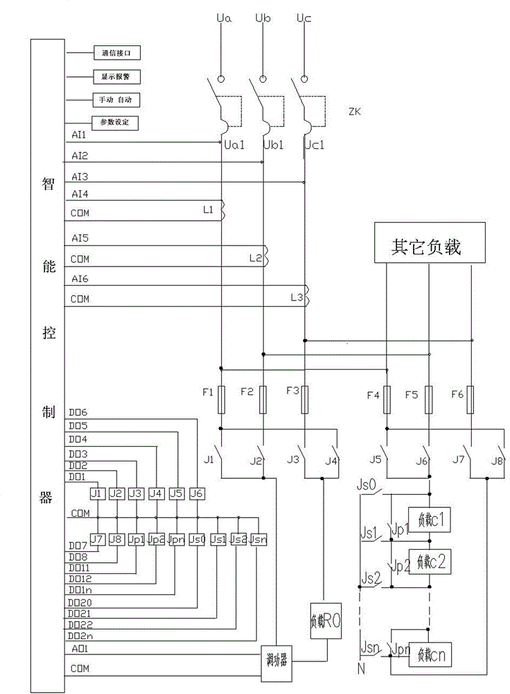
[0070] Figure 9 It is the principle wiring diagram of the system of Embodiment 1 of the present invention: it includes a cabinet and a main switch ZK, three current sampling circuits, an intelligent controller, six fuses F1-F6, seven contactors J1- J7, the four heating elements Rab, Rbc, Rca, R0 are heating wires with the same power and the same power added between phases. The current sampling is composed of three transformers La, Lb, and Lc used to detect three-phase current loads. One end of them is respectively connected to the input ends of AI4, AI5, and AI6 of the intelligent controller, and the other ends are connected together. After that, connect it to the COM terminal of the power controller. The intelligent controller is provided with a communication interface. The upper end of the main switch ZK is connected to the main power supply Ua, Ub, Uc, one end of the fuses F1-F6 is connected to the lower ends Ua1, Ub1, Uc1 of the main switch in turn, and the other ends o...

Embodiment 2

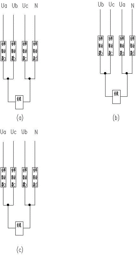
[0077] Figure 10 It is the principle wiring diagram of the system of Embodiment 2 of the present invention, which includes a cabinet and a main switch ZK, three current sampling circuits, an intelligent controller, six fuses F1-F6, and three transformers L1-L3 are installed in the cabinet , Six single-phase contactors, four heaters, this scheme is generally used in small current or high voltage occasions, here for 10KV electric heating occasions. The connection method of the upper ends of the six fuses F1-F6 and other loads and figure 1 The same will not be repeated here. The lower ends of the fuses F1-F3 are connected to one end of the contactors J1, J2, and J3 in sequence, and the other ends of the contactors are respectively connected to one end of the A-phase heater, B-phase heater, and C-phase heater; the other end of the three-phase heater One end is connected together and then connected to one end of C contactor J7, the other end of J7 is connected to the neutral lin...

Embodiment 3

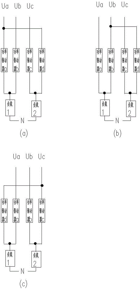
[0081] Figure 11 It is the principle wiring diagram of the system of Embodiment 3 of the present invention, which includes a cabinet and a main switch ZK, three current sampling circuits, three voltage sampling circuits, an improved multi-functional electric meter, six fuses F1- F6, two conversion relays, five relays, and three power capacitors. It is used for reactive power compensation at the end of single-phase load, not only can compensate reactive power, but also can balance active power. The voltage sampling circuit is a wire connected to the load power supply and the power controller respectively, and one end of them is respectively connected to the input ends of AI1, AI2, and AI3 of the multi-function electric meter. The connection method of the upper ends of the six fuses F1-F6 and other loads and figure 1 The same will not be repeated here. The lower end of the fuse F1 is connected to the contact of the transfer relay J1-1 and the contact of J2-2, and the lower e...


PUM


Abstract

Disclosed is a single-phase load control device and method. The device at least comprises two change-over switches or a plurality of single-phase power drivers, which are connected to a three-phase power supply and single-phase loads controlled by the single-phase power drivers. The device is characterized in that the single-phase power drivers connected to the three-phase power supply are connected to two sides of each single-phase load, respectively; the single-phase power drivers on one side are connected to any two phases of the three phases of A, B, C; the single-phase power drivers on the other side are connected to the left phase and any one phase of the two phases; or the single-phase power drivers on the other side are connected to the left phase and a zero-line phase. As a result, each single-phase load is added between any two phases, or a redundant load is added between any one phase and the ground via three single-phase power drivers. The single-phase load control device can be used for active adjustment and reactive compensation, and achieves purposes of balancing three-phase load, improving reliability of a system, and saving energy.

Description

technical field [0001] The invention provides a single-phase load control device in a three-phase power system and a control method thereof, and particularly relates to controlling a single-phase thermal single-phase load to improve the reliability, flexibility and regulation ability of the control system. Background technique [0002] In the existing three-phase power system, the control method for single-phase load cannot realize simple and flexible selective control, and it is difficult to achieve the goals of high reliability and energy saving. Contents of the invention [0003] Purpose of the invention: The present invention provides a single-phase load control device and its control method in a three-phase power system. Control issues for high performance and energy saving purposes. [0004] The invention can be used to balance active power and compensate reactive power to achieve the purpose of ensuring three-phase balance, safety and energy saving. [0005] Techn...

Claims


Application Information

Patent Timeline
Patent Type & Authority Applications(China)
IPC IPC(8): H02J3/00H02J3/26H02J3/18
CPCY02E40/30Y02E40/50
Inventor 冯志宇齐治文其他发明人请求不公开姓名
Owner 周帅
Why Eureka
Try Eureka