Internal combustion engine control circuit and internal combustion engine control method

A technology of internal combustion engine control and internal combustion engine, which is applied in the direction of motor starting for engines, machines/engines, mechanical equipment, etc., and can solve problems such as power reduction and other problems

Active Publication Date: 2015-09-02
SHINDENGEN ELECTRIC MFG CO LTD
View PDF4 Cites 7 Cited by
  • Summary
  • Abstract
  • Description
  • Claims
  • Application Information

AI Technical Summary

Problems solved by technology

[0004] However, as disclosed in Japanese Patent Application Laid-Open No. 2005-188444, if an electric storage body such as a capacitor (Capacitor) is usually set in a connected state in advance, a so-called

Method used


Image

  • Internal combustion engine control circuit and internal combustion engine control method
  • Internal combustion engine control circuit and internal combustion engine control method
  • Internal combustion engine control circuit and internal combustion engine control method

Examples


Embodiment approach 1

[0033] "structure"

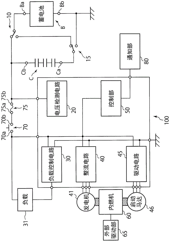
[0034] Hereinafter, Embodiment 1 of the internal combustion engine control circuit according to the present invention will be described with reference to the drawings. here, Figure 1 to Figure 6 It is a figure for demonstrating embodiment of this invention.

[0035] The internal combustion engine control circuit 100 of the present embodiment is, for example, a circuit for controlling an internal combustion engine 60 such as an engine, for example, a circuit for controlling a motor of a motorcycle engine can be taken as an example. As will be described later, the internal combustion engine 60 of the present embodiment can be started by driving an external drive unit 65 such as a kick starter. In addition, instead of using such an external drive unit 65 when starting the internal combustion engine 60, the internal combustion engine 60 may be started by, for example, pushing the motorcycle vigorously (so-called "push starter"). Such as figure 1 As shown...

Embodiment approach 2

[0078] Next, Embodiment 2 will be described. in addition, Figure 7 is a basic configuration diagram showing the internal combustion engine control circuit 100 according to Embodiment 2 of the present invention, and shows the same Figure 5 corresponding form.

[0079] In Embodiment 1, when the main switch 70 is on and the voltage generated by the generator 41 is higher than the voltage when the battery B is fully charged, as Figure 5 It is shown that the first terminal Ca of the capacitor C is connected to ground through the second switch 15, and the first terminal Ba of the battery B is connected to the second terminal 70b of the main switch 70 and the capacitor C via the fuse 75 through the first switch 10, A form in which the storage battery B and the capacitor C are connected in parallel so that both the storage battery B and the capacitor C can be charged. Regarding this point, in the second embodiment, a rotational speed detection circuit 95 for detecting the rotati...


PUM


Abstract

When a main switch (70) is in an off state, a control unit (50) connects one end of a capacitor (C) to a first switch (10) by means of a second switch (15) and disconnects one end of a battery (B) and the second switch (15) from each other by means of the first switch (10). When a starter motor (46) is to be activated by bringing the main switch (70) into an on state, the one end of the capacitor (C) is connected to the first switch (10) by the second switch (15), and the one end of the battery (B) is connected to the second switch (15) by the first switch (10), thereby connecting the battery (B) to the capacitor (C) in series. Once the internal combustion engine (60) has started up, the one end of the capacitor (C) is connected to the first switch (10) by the second switch (15), and the one end of the battery (B) and the second switch (15) are disconnected from each other by the first switch (10).

Description

technical field [0001] The present invention relates to an internal combustion engine control circuit for controlling an internal combustion engine such as an engine (Engine), and an internal combustion engine control method using the internal combustion engine control circuit. Background technique [0002] Conventional internal combustion engine control circuits, such as Figure 8 The internal combustion engine control circuit shown in . Such as Figure 8 As shown, the internal combustion engine control circuit connected to the battery (Battey) B includes: a load control circuit 130 that controls the load 131, a rectifier circuit 140 that rectifies the current generated by the generator 141, and a starter motor (Cell Motor) driven The driving circuit 145, and the control unit 150 connected to and controlling the load control circuit 130, the rectifying circuit 140 and the driving circuit 145. In addition, in the Figure 8 In the illustrated form, a main switch (Main Switch...

Claims


Application Information

Patent Timeline
IPC IPC(8): F02N11/08
CPCF02N11/04F02N11/0866F02N11/08F02N2011/0885
Inventor 岡本章広新井逹也
Owner SHINDENGEN ELECTRIC MFG CO LTD
Why Eureka
Try Eureka