
Charging member, processing cartridge, and electrophotographic image forming apparatus

A technology of charging components and electrophotography, applied in the direction of equipment, thin material processing, electrical components, etc. of the electric recording process applying charge patterns, capable of solving problems such as image defects, uneven charging and charging

Active Publication Date: 2015-09-02
CANON KK
View PDF5 Cites 2 Cited by
  • Summary
  • Abstract
  • Description
  • Claims
  • Application Information

AI Technical Summary

Problems solved by technology

[0003] Due to the electric energy intermittently applied to the charging member of the electrophotographic image forming apparatus (hereinafter, also referred to as “electrophotographic apparatus”), the resistance of the charging member gradually changes, causing uneven charging and charging defects, which in some cases lead to image defect

Method used


Image

  • Charging member, processing cartridge, and electrophotographic image forming apparatus
  • Charging member, processing cartridge, and electrophotographic image forming apparatus
  • Charging member, processing cartridge, and electrophotographic image forming apparatus

Examples


Embodiment 1

[0141]

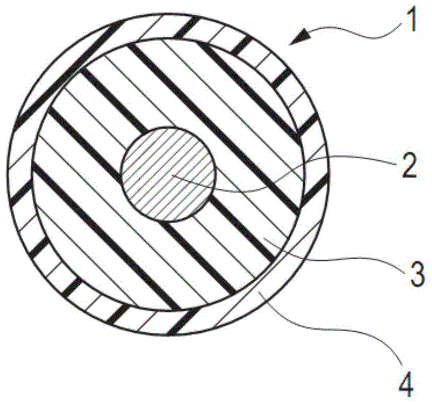
[0142] An elastic roller having an elastic layer on a conductive support was produced as follows.

[0143] A stainless steel rod having a diameter of 6 mm and a length of 252.5 mm was coated with a thermosetting adhesive (trade name: METALOC U-20, manufactured by Toyokagaku Kenkyusho Co., Ltd.), and then dried to be used as a conductive support.

[0144] In producing the raw rubber composition for the rubber elastic layer, the materials shown in Table 4 below were kneaded for 15 minutes with a 6-liter internal mixer adjusted to 50°C. In Table 4, EO represents ethylene oxide, EP represents epichlorohydrin, and AGE represents allyl glycidyl ether.

[0145] Table 4

[0146]

[0147] The materials described in Table 5 below were added to the above, and kneaded for 10 minutes with a two-roll mill cooled at 25° C., thereby preparing a raw rubber composition.

[0148] table 5

[0149] Material

parts by mass

sulfur as vulcanizing agent

1.2

...

Embodiment 2-5

[0166]

[0167] Charging rollers (2)-(5) were obtained in the same manner as in Example 1, except that the addition amount of epigallocatechin gallate used to manufacture the surface layer paint (1) was changed as shown in Table 8.

Embodiment 6

[0169]

[0170] A charging roller (6) was obtained in the same manner as in Example 1 except that the surface layer paint (1) was changed to the following surface layer paint (2).

[0171]

[0172] A surface layer paint containing a nylon resin as a binder resin was prepared as follows.

[0173] First, 200 g of a mixed solution containing the materials described in Table 7 below and 200 g of glass beads with a central particle diameter of 0.6 mm to 0.85 mm as a dispersion medium (after being sieved with a sieve with a sieve opening of 0.85 mm and further sieved with a sieve After sieving with a 0.65 mm sieve, glass beads remaining on the 0.65 mm sieve) were put into a glass bottle with a capacity of 450 mL, and dispersed with a paint shaker for 24 hours to obtain a dispersion.

[0174] Table 7

[0175] Material

[0176] Subsequently, 0.19 g of epigallocatechin gallate (0.5 parts by mass relative to 100 parts by mass of methoxymethylated nylon solid content) was...


PUM


Abstract

A charging member is provided, suppressing the occurrence of streak-like images resulting from resistance increase caused by degradation of the charging member due to electric conduction for a long period. A process cartridge and an electrophotographic apparatus are also provided, suppressing the occurrence of streak-like images and stably forming a high-quality electrophotographic image. The charging member comprises an electroconductive support and an electroconductive surface layer, the surface layer comprising at least one of the compounds respectively represented by formula (1), formula (3), and formula (4) defined in the specification, a binder resin, and a conducting agent. The process cartridge and the electrophotographic apparatus use the charging member.

Description

technical field [0001] The present invention relates to a charging member, a process cartridge, and an electrophotographic image forming apparatus. Background technique [0002] In an image forming apparatus using the electrophotography method, a charging member charges an electrophotographic photosensitive member (hereinafter, also referred to as “photosensitive member”) to a predetermined potential. The charging member generally includes an elastic body such as rubber or elastomer, the surface of which is provided with a surface layer of, for example, crosslinked polyurethane. A conductive agent is dispersed in the surface layer to impart conductivity. [0003] Due to the electric energy intermittently applied to the charging member of the electrophotographic image forming apparatus (hereinafter, also referred to as “electrophotographic apparatus”), the resistance of the charging member gradually changes, causing uneven charging and charging defects, which in some cases l...

Claims


Application Information

Patent Timeline
Patent Type & Authority Applications(China)
IPC IPC(8): G03G15/02
CPCG03G15/0233Y10T428/31551G03G15/0208
Inventor 松田秀和宫川昇
Owner CANON KK
Features
  • Generate Ideas
  • Intellectual Property
  • Life Sciences
  • Materials
  • Tech Scout
  • Unparalleled Data Quality
  • Higher Quality Content
  • 60% Fewer Hallucinations
Learn More