Vertical continuous discharge sedimentation centrifuge

A settling centrifuge and centrifuge technology, applied to centrifuges, centrifuges with rotating drums, etc., can solve the problems of low moisture content, unsatisfactory speed difference, and poor speed, and achieve simple production and manufacturing , the control part is simple, and the speed difference ratio is constant

Active Publication Date: 2019-04-30
NINGBO RONGDA ENVIRONMENTAL PROTECTION EQUIP
View PDF11 Cites 0 Cited by
  • Summary
  • Abstract
  • Description
  • Claims
  • Application Information

AI Technical Summary

Problems solved by technology

[0004] After many years of use, it has been found that the horizontal screw discharge decanter centrifuge with the above structure has a defect, that is, the drum and the screw pusher in the prior art horizontal screw discharge decanter centrifuge are connected by a differential , and use the main and auxiliary motors to control the speed of the drum and the screw propeller respectively through the frequency converter to achieve the speed difference between them. Factors such as the amount of material and fluctuations will affect the load of the screw propeller, so that the adjusted speed difference will change, causing the control part of the centrifuge to continuously detect, adjust, and compensate to ensure the stability of the speed difference. The control part of the centrifuge becomes very complicated
For this reason, people also can simply use the speed changer to complete the speed difference between the drum and the screw pusher, but the speed difference is not satisfactory. According to some reports, a speed changer of 1 / 125 can be made at present, that is, It is said that a speed difference of 24 rpm can be obtained at a speed of 3000 rpm. We know that the smaller the speed difference, the less the moisture content of the solid material. Some centrifuges even require a speed difference lower than 7 rpm. Such a transmission is difficult to manufacture. The reason is that in order to achieve a small speed difference, the number of gear teeth in the transmission is required to be relatively large, and under a certain gear modulus, the outer diameter of the gear will increase. If it is made very large, it will not only increase the volume of the transmission and the centrifuge, but also bring some troubles to the production of the centrifuge.
[0005] In addition, the drum and the screw pusher in the prior art horizontal screw unloading decanter centrifuge are all checked and processed for dynamic balance without material. When the fluid material is added, due to the gravity The dynamic balance of the drum and the screw pusher is easily affected or even resonates

Method used


Image

  • Vertical continuous discharge sedimentation centrifuge

Examples


Embodiment Construction

[0016] The vertical continuous unloading sedimentation centrifuge of the present invention will be further described below in conjunction with the drawings and specific embodiments:

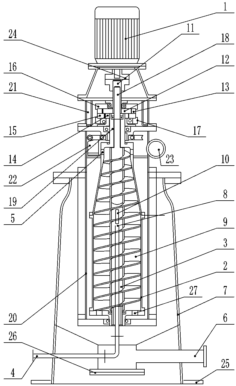
[0017] Such as figure 1 As shown, the vertical continuous discharge sedimentation centrifuge of the present invention includes a motor 1, a rotating drum 2, a screw pusher 3, a feed pipe 4, a slag outlet 5, a liquid outlet 6, an overflow port 27, and a base 7. And the centrifuge housing 20. The feed pipe 4 communicates with the distribution chamber 8 in the screw pusher 3, and the screw pusher 3 is provided with a discharge port 10 communicating with the drum cavity 9 of the rotating drum 2. The centrifuge housing 20 is vertically installed on the base 7, and the motor 1 is installed on the top of the centrifuge housing 20. The liquid outlet 6 and the inlet of the feed pipe 4 are both located below the centrifuge housing 20, the slag outlet 5 is arranged at the upper small end of the rotating drum...


PUM


Abstract

A vertical continuous discharging sedimentation centrifuge comprises a motor, a drum, a spiral pushing device, a feeding pipe, a slag outlet, a liquid outlet, an overflow opening, a base and a centrifuge casing; the feeding pipe is communicated with a distribution chamber which is formed in the spiral pushing device; the spiral pushing device is provided with a discharging hole which is communicated with a drum chamber of the drum; the centrifuge casing is arranged on the base; the motor is arranged on the centrifuge casing; an output shaft of the motor is connected with an input shaft which is arranged on the spiral pushing device; an output shaft which is arranged at one end of the drum is connected with the input shaft in a rotatable mode; the other end of the drum is connected with the centrifuge casing and the spiral pushing device in a rotatable mode; a differential gear shifting mechanism is arranged between the input shaft which is arranged on the spiral pushing device and the output shaft which is arranged on the drum. According to the vertical continuous discharging sedimentation centrifuge, the differential rate between the drum and the spiral pushing device can be small and constant, the control portion of the centrifuge is simple, the centrifuge can be compact in structure, the size can be reduced, and production and manufacture can be simple.

Description

Technical field [0001] The invention relates to a solid-liquid separation equipment, in particular to a vertical continuous discharge sedimentation centrifuge. . Background technique [0002] Centrifuge is a solid-liquid separation equipment that uses centrifugal force to separate solid particles in suspension from liquid. It is mainly used in the chemical, mineral processing, petroleum, pharmaceutical, food and other industries, as well as the treatment of odorous sewage. When the suspension is separated by sedimentation. At present, the conventional centrifuges are mainly horizontal spiral unloading sedimentation centrifuges, which mainly include a frame, a rotating drum, a screw pusher, a differential, a feed tube, a main motor, an auxiliary motor, and two The frequency converter that controls the speed of the main motor and the auxiliary motor respectively. The rotating shafts at both ends of the drum are supported on the frame respectively. The input shaft of the drum is c...

Claims


Application Information

Patent Timeline
Patent Type & Authority Patents(China)
IPC IPC(8): B04B1/20B04B7/00B04B9/08B04B9/10
Inventor 罗名杨徐永安罗逸之
Owner NINGBO RONGDA ENVIRONMENTAL PROTECTION EQUIP
Why Eureka
Try Eureka