

Device for machining slender shaft
A slender shaft, cutting device technology, used in metal processing equipment, manufacturing tools, accessories for tool holders, etc.
Inactive Publication Date: 2015-09-09
GUIZHOU HANGRUI AVIATION PRECISION PARTS MFG
View PDF9 Cites 4 Cited by
- Summary
- Abstract
- Description
- Claims
- Application Information
AI Technical Summary
Problems solved by technology
[0004] The present invention provides a device for processing slender shafts, aiming at the shortcomings in the processing of the above-mentioned slender shaft parts; through the use of small parts, the problem of radial and axial cutting forces is solved at the same time, which is beneficial to the prevention of slender shafts. On the basis of the processing deformation of the workpiece, a better processing effect can be achieved
Method used
View moreImage
Smart ImageViewing Examples

Examples
Embodiment Construction
[0017] Below in conjunction with accompanying drawing and embodiment the technical solution of the present invention is further described:
Login to View More PUM
 Abstract
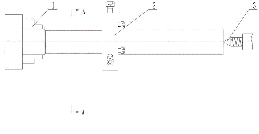
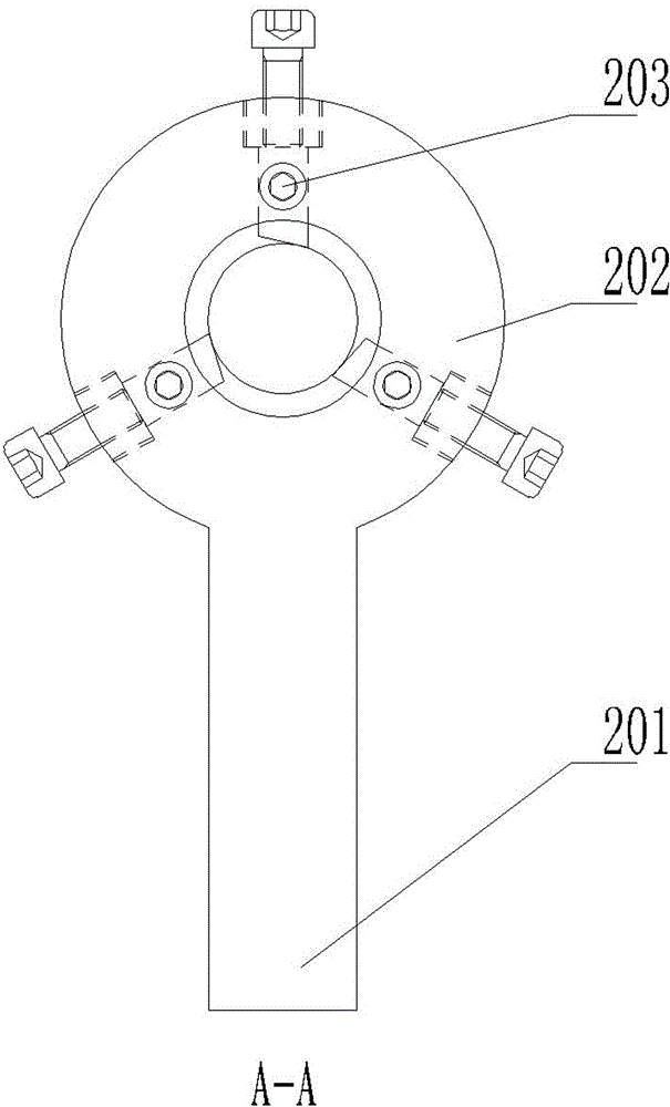
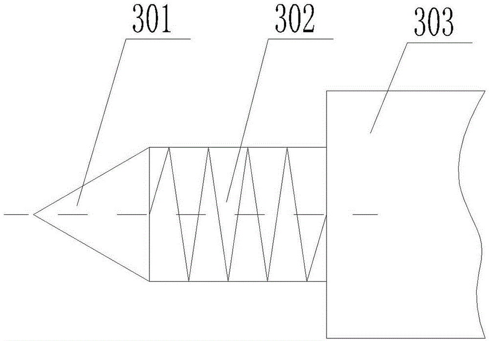
The invention discloses a device for machining a slender shaft. The device comprises a fixture and a cutting device, the fixture is used for fixing the slender shaft, the cutting device is used for cutting the slender shaft, the fixture comprises a chuck and a tip which are used in a matched manner, an ejector pin is an elastic tip and comprises a tip head, a tip body and an elastic component positioned in the tip body, the cutting device comprises a cutter handle, a cutter head and turning tool components, the cutter head is connected with the cutter handle, the turning tool components are uniformly distributed on the cutter head, each turning tool component comprises a square hole, a positioning device and an adjusting device, and the square holes for mounting blades are formed in the cutter head. The cutter head is a small part, small in size, light in weight and applicable to a common latch, the problems of radial and axial cutting force can be simultaneously solved, the device has an excellent effect for effectively preventing machining deformation of a slender shaft workpiece, and machining accuracy of parts is effectively improved.
Description
technical field [0001] The invention belongs to the field of machining and manufacturing, and in particular relates to a device for machining slender shafts. Background technique [0002] A shaft with a ratio of length to diameter greater than 25 is called a slender shaft. Such parts are generally processed on a lathe. Due to their poor rigidity, the slender shaft is prone to bending deformation under the action of cutting force, gravity, and cutting heat during turning, resulting in the elongation direction of the slender shaft and the path of the cutting device. Not on the same axis, which destroys the accuracy of the relative movement of the cutting device and the parts, and makes the processed slender shaft have a shape with a thick middle and thin ends, which seriously affects the machining accuracy of the parts. At the same time, after the slender shaft is bent and deformed, the precision of the processed parts is not high, and the shape of the deformed slender shaft ...
Claims
Login to View More Application Information
Patent Timeline
 Patent Type & AuthorityApplications(China)
IPC IPC(8): B23B5/08B23B23/00
CPCB23B5/08B23B23/00
Inventor王世敏
OwnerGUIZHOU HANGRUI AVIATION PRECISION PARTS MFG