Unlock instant, AI-driven research and patent intelligence for your innovation.

Screw automatic supply device

An automatic feeding and screw technology, which is applied in vibrating conveyors, transportation and packaging, conveyors, etc., can solve the problems of large space occupation, complex structure, and increased volume of the roller mechanism, and achieves easy installation, reduced space occupation, and volume Reduced effect

Active Publication Date: 2015-09-09
KUNSHAN RONGYI AUTOMATION EQUIP
View PDF8 Cites 21 Cited by
  • Summary
  • Abstract
  • Description
  • Claims
  • Application Information

AI Technical Summary

Problems solved by technology

The screw supply device in the prior art is expensive in maintenance due to its size and complex structure, and because the whole machine needs a considerable space to be placed, it is unfavorable to use when the work site changes. At the same time, in the prior art The existing screw supply device also has the following deficiencies:
[0003] 1) The transmission shaft is directly installed on the shaft end of the drum motor. After the whole mechanism is installed on the bottom plate of the screw machine, it takes up a lot of space, and the assembly steps are cumbersome, which brings inconvenience to the later dismantling and maintenance.
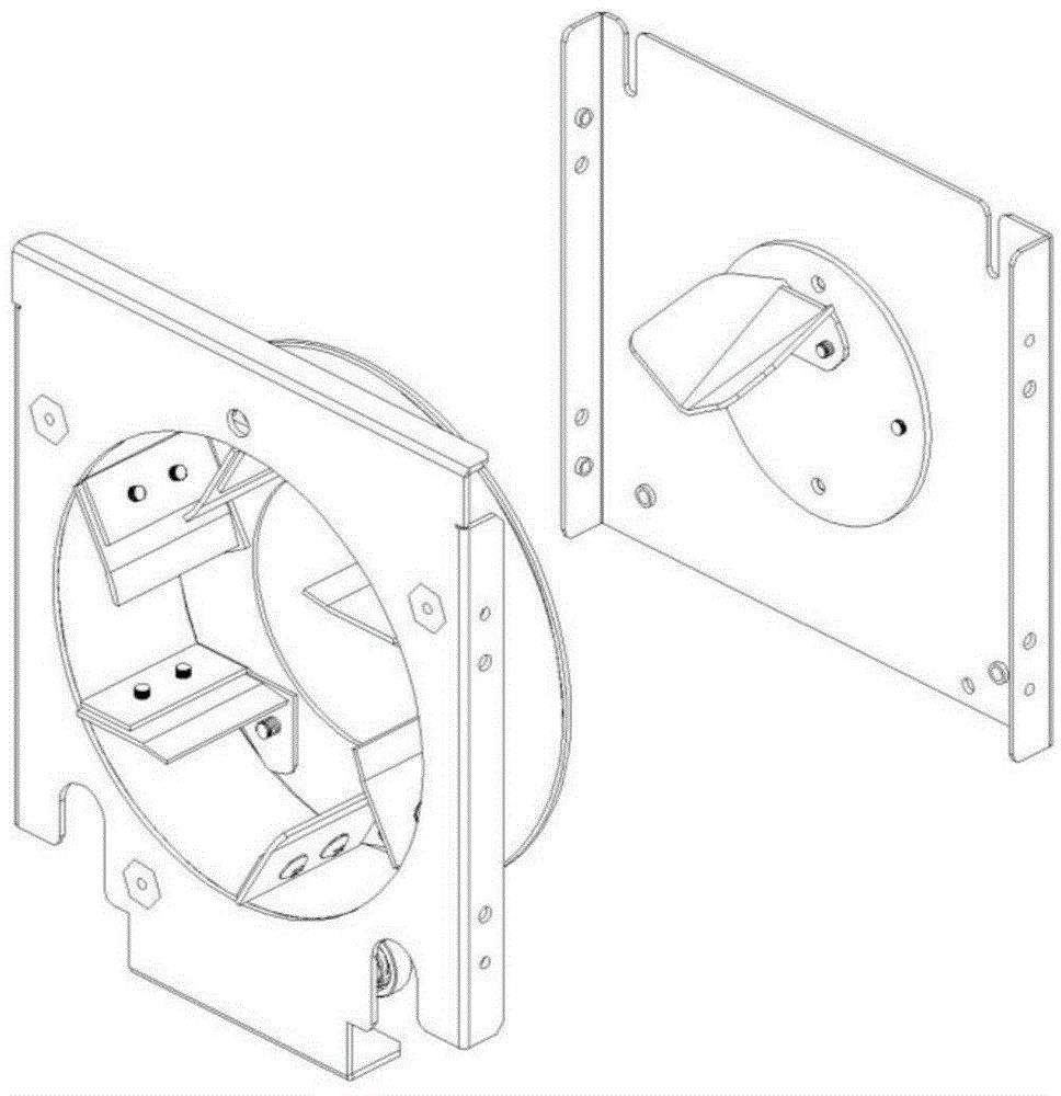
[0004] 2) The scraping plate in the drum needs to be installed separately, which increases the assembly process of the drum mechanism, see figure 1
In order to increase the amount of scraping material, the size of the scraping plate is larger, which increases the volume of the entire drum mechanism and takes up a lot of space

Method used


Image

  • Screw automatic supply device
  • Screw automatic supply device
  • Screw automatic supply device

Examples


Embodiment Construction

[0039] The present invention will be further described in detail below in conjunction with the accompanying drawings and embodiments.

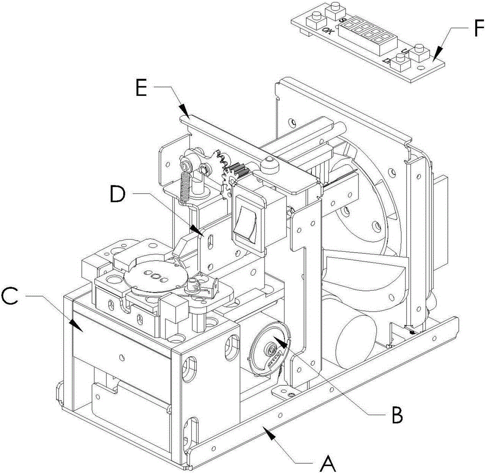
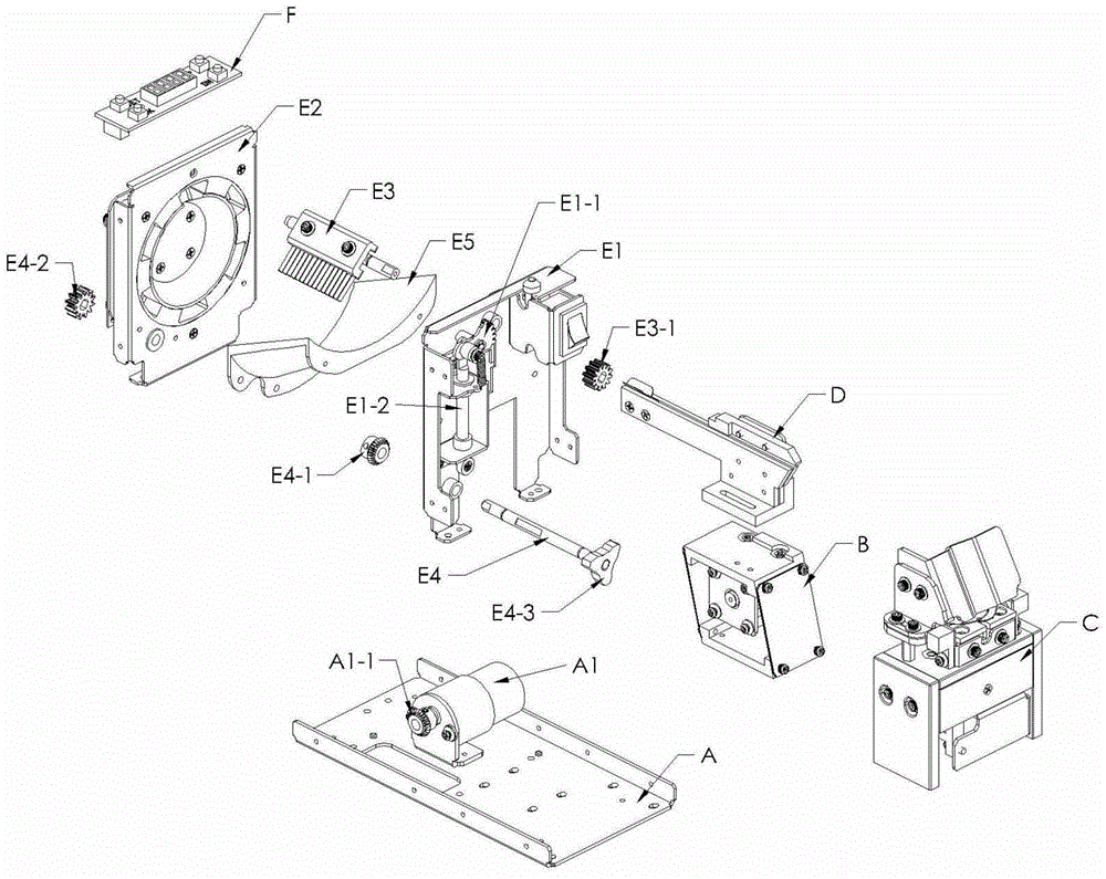
[0040] Please see first Figure 2-Figure 3 , figure 2 It is a structural schematic diagram of the screw component automatic supply device of the present invention, image 3It is an exploded view of the automatic screw component supply device of the present invention. As shown in the figure, an automatic screw supply device includes a casing, a bottom plate A, an orbital vibration seat B placed in the casing, an indexing plate rotation mechanism C, and a screw track D. Tank chamber E and control and display panel F. A roller motor A1 is installed on the bottom plate A; the screw falls into the screw track D through the trough chamber E, and the screw track D is installed on the track vibration seat B, and the screw is on the The said screw tracks D are neatly arranged and vibrated forward, and reach the said index rotating mechanism C, wher...


PUM


Abstract

A screw automatic supply device comprises a shell body base plate, a track vibration base put inside a shell body, a dividing disc rotary mechanism, a screw track, a material groove chamber and a control and display plate, wherein screws fall on the screw track through the material groove chamber; the screw track is mounted on the track vibration base; the screws are tidily arranged on the screw track and moved forward in a vibration way; and after arriving the dividing disc rotary mechanism, the screws are discharged out one by one for next use in the dividing rotary mechanism. According to the invention, the volume of a rolling cylinder mechanism is greatly reduced; separate removal can be carried out aiming to a rolling cylinder motor or a rotary shaft; and the accuracy and stability of supplying the screws are ensured.

Description

technical field [0001] The invention belongs to the technical field of automation equipment, in particular to an automatic screw supply device. Background technique [0002] In mechanical work, screws are indispensable elements, how to supply screws quickly, conveniently and neatly is the technical problem to be solved in this application. The screw supply device in the prior art is expensive in maintenance due to its size and complex structure, and because the whole machine needs a considerable space to be placed, it is unfavorable to use when the work site changes. At the same time, in the prior art The existing screw supply device also has the following deficiencies: [0003] 1) The transmission shaft is directly installed on the shaft end of the drum motor. After the whole mechanism is installed on the bottom plate of the screw machine, it takes up a lot of space, and the assembly steps are cumbersome, which brings inconvenience to the later dismantling and maintenance....

Claims


Application Information

Patent Timeline
IPC IPC(8): B65G47/74B65G27/34
CPCB65G27/34B65G47/74
Inventor 徐振凯
Owner KUNSHAN RONGYI AUTOMATION EQUIP