
A combined ladder key structure and its construction method

A construction method and a combined technology, which is applied in the direction of foundation structure engineering, excavation, construction, etc., can solve the problem of insufficient durability and reliability of landslide or slope treatment, loss of prestressed relaxation of anchor cables, and restrictions on the effective use of anti-slide piles, etc. problems, to achieve the effect of improving collaborative work ability, reducing project cost, and excellent support ability

Inactive Publication Date: 2017-01-04
CHONGQING JIAOTONG UNIVERSITY +1
View PDF6 Cites 0 Cited by
  • Summary
  • Abstract
  • Description
  • Claims
  • Application Information

AI Technical Summary

Problems solved by technology

The existing technology has the following technical problems: First, the measures to increase the cross-sectional area of ​​the anti-slide pile and the amount of reinforcement not only require a large amount of engineering and high treatment costs, but also make the on-site construction more difficult when restricted by the red line of the land or the space of existing buildings , which limits the effective use of traditional anti-slide piles; the second is to set the prestressed anchor cable measures on the pile body. Due to the high cost of the anchor cable and the prestress relaxation loss and corrosion phenomenon of the anchor cable, the durability of landslide or slope control and the Significant lack of reliability
At the same time, the anti-slide piles of the prior art are generally independent of each other, causing some anti-slide piles to bear a large landslide thrust, while some anti-slide piles are in an empty state, resulting in unreasonable utilization of resources and potential increase. project cost

Method used


Image

  • A combined ladder key structure and its construction method
  • A combined ladder key structure and its construction method
  • A combined ladder key structure and its construction method

Examples


Embodiment 1

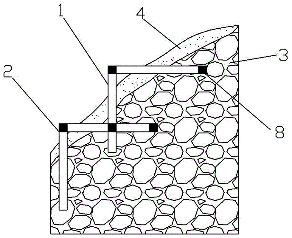
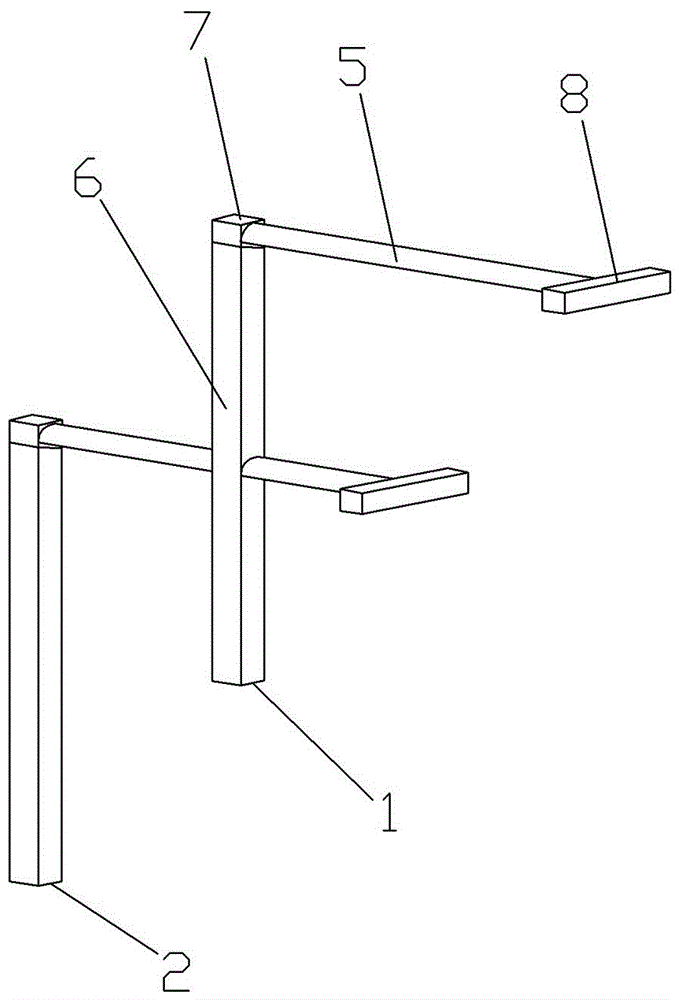
[0037] Such as Figure 1 to Figure 5As shown, the present invention provides a combined ladder key structure, comprising an upper ladder key unit 1 and a lower ladder key unit 2, and both the upper ladder key unit 1 and the lower ladder key unit 2 include a horseshoe-shaped cross arm 5, a rectangular vertical leg 6 and The horizontal locking key 8, the rectangular vertical leg 6 and the horizontal locking key 8 are all rectangular in cross-section, and the cross-section of the horseshoe-shaped cross arm 5 is horseshoe-shaped. , the other end of the horseshoe-shaped cross arm 5 is placed into the bedrock 3 and is perpendicular to the horizontal locking key 8 and is rigidly connected; the upper ladder key unit 1 and the lower ladder key unit 2 are connected in a ladder shape, and the rectangular vertical The leg 6 and the horseshoe-shaped cross arm of the lower ladder key unit 2 are vertically intersected and connected rigidly; The pile end rigid connection portion 7 of the ver...

Embodiment 2

[0049] The present invention provides a combined ladder key structure, including an upper ladder key unit and a lower ladder key unit. The difference between Embodiment 2 and Embodiment 1 is that the length of the stable bedrock insertion section of the horseshoe-shaped cross arm is set to 8m. The length of the horizontal locking key is 4 times the width of the rectangular vertical leg. The cross-sectional areas of the rectangular vertical leg and the horizontal locking key are both rectangular and equal in size. The cross-section of the pile body of the rectangular vertical leg and the horizontal locking key The length is 4m, the width is 3m, and the inner space of the pile body of the horseshoe-shaped transverse arm is 0.5m.

[0050] A construction method of a combined ladder key structure, the difference from the embodiment is that in step b: welding and binding the rectangular vertical legs of the upper ladder key unit to the reinforcement cage, using segmental binding of s...

Embodiment 3

[0052] Such as Figure 6 and Figure 7 As shown, the present invention provides a combined ladder key structure, which is different from Embodiment 1 in that: between the upper ladder key unit 1 and the lower ladder key unit 2, there is also a device connecting the upper ladder key unit 1 and the lower ladder key unit. The middle ladder key unit 10 of unit 2, the upper ladder key unit 1, the lower ladder key unit 2 and the middle ladder key unit 10 all include a horseshoe-shaped cross arm, a rectangular vertical leg and a horizontal locking key; the cross section of the rectangular vertical leg and the horizontal locking key They are all rectangular, and the cross-section of the horseshoe-shaped cross-arm is horseshoe-shaped. One end of the horseshoe-shaped cross-arm exposes the sliding body and is rigidly connected and fixed on the top of the rectangular vertical leg. Rigid connection, the horseshoe-shaped cross arm, rectangular vertical leg and horizontal locking key are al...


PUM


Abstract

The invention relates to the technical field of landslide control and foundation pit support, and concretely relates to a combined ladder key structure and a construction method. The combined ladder key structure comprises ladder key units. Each ladder key unit is formed by a U-shaped cross arm, a rectangular vertical leg and a transverse locking key, wherein one end of the U-shaped cross arm is exposed out of a slide body and rigidly connected to the top of the rectangular vertical leg; the other end of the U-shaped cross arm is placed in a base rock, perpendicular to and in a rigid connection with the transverse locking key; adjacent ladder key units are connected in a stair shape; the rectangular vertical leg of the ladder key unit on the upper part vertically inserted through U-shaped cross arms of the ladder key units on the lower part, and rigidly connected to the same; and the U-shaped cross arm, the rectangular vertical legs and the transverse locking keys are all made from reinforced concrete. By the use of the combined ladder key structure and the construction method, great slide resistance performance, small engineering work, simple construction, low cost and great supporting effect can be achieved.

Description

technical field [0001] The invention relates to the technical field of landslide control and foundation pit support, in particular to a combined ladder key structure and construction method. Background technique [0002] Anti-slide piles are widely used in landslide control and slope protection due to their high rigidity, good stability, convenient construction, and strong anti-slip performance. The working principle of the anti-slide pile is mainly to drive the pile into the bedrock at a certain depth from the slope, and to balance the landslide of the free end of the rock and soil by means of the embedding effect and passive resistance of the rock and soil at the embedded end of the bedrock. Thrust or slope pressure to maintain landslide or slope stability. [0003] In the current design of anti-slide piles, most of them are based on the straight pile structure, and the understanding and use of the full utilization of the rock and soil mass behind the pile and the optimiz...

Claims


Application Information

Patent Timeline
Patent Type & Authority Patents(China)
IPC IPC(8): E02D17/04E02D17/20
Inventor 王羽赵波柴贺军翟永超于远志王富强付有为徐航杨军
Owner CHONGQING JIAOTONG UNIVERSITY
Learn More