Method for reducing maximal pressure of rail shared injector

A technology of maximum pressure and injector, applied in the direction of fuel injection control, fuel injection device, machine/engine, etc., can solve problems such as affecting the function of the injector, and achieve the effect of timely identification and reduction of manufacturing costs

Inactive Publication Date: 2015-09-09
ROBERT BOSCH GMBH
View PDF5 Cites 1 Cited by
  • Summary
  • Abstract
  • Description
  • Claims
  • Application Information

AI Technical Summary

Problems solved by technology

But this clearly and undesirably affects the injector function

Method used


Image

  • Method for reducing maximal pressure of rail shared injector
  • Method for reducing maximal pressure of rail shared injector

Examples


Embodiment Construction

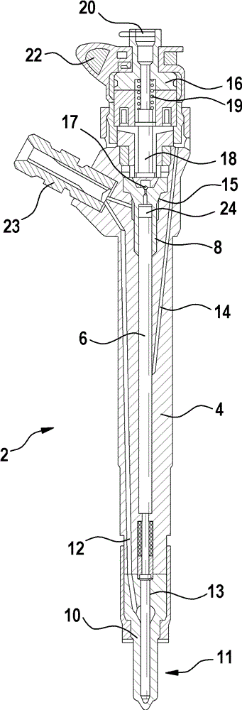
[0015] figure 1 An embodiment of a common rail injector 2 according to the prior art is shown. A schematic sectional view of a common rail injector 2 is shown. The common rail injector 2 comprises an injector body 4 , in which a valve piston 6 is arranged, which is guided at an upper end in a valve block 8 and whose lower end extends toward a nozzle 10 . The nozzle needle 11 is coupled to the valve piston 6 and is arranged inside the nozzle 10 . A magnetic head 16 , an armature assembly 18 and a return connection 20 are arranged at the upper end of the common rail injector 2 . Furthermore, the common rail injector 2 is connected to a power supply via an electrical connection 22 and to a fuel supply line via a high-pressure inlet 23 , which includes a dust filter.

[0016] The nozzle needle 11 is guided within the nozzle 10 in a nozzle needle guide 13 . The nozzle needle guide 13 essentially consists of a precisely drilled hole in the nozzle 10 , in which the nozzle needle ...


PUM


Abstract

According to the embodiments of the invention, a method for reducing maximal pressure of rail shared injector in fault condition is provided. When a fault condition (31) is spotted, a special operation mode is initialized (32) for at least one rail shared injector (2). In this way, the maximal pressure in fault condition can be reduced without modifying other high voltage components or the design of rail shared injector. For these innovations, expensive manufacturing costs of injector (4), valve blocks (8) and injection nozzles (10) can be avoided.

Description

technical field [0001] The invention relates to a method for reducing the maximum pressure of at least one common rail injector of a motor vehicle. Furthermore, the present invention relates to a computer program for carrying out each step of the method according to the invention if said computer program is run on a computer and to a machine-readable storage medium, The storage medium stores the computer program. Furthermore, the invention relates to an electronic controller which is designed to carry out the method according to the invention. Background technique [0002] A common rail system is a fuel injection system for diesel internal combustion engines of motor vehicles. The core component of the common rail system is the common rail injector connected to the rail ("common rail"). The common rail injectors each include a fast-switching servo valve, the switching state of which controls the opening and closing of an injection nozzle. The injection process can thus b...

Claims


Application Information

Patent Timeline
Patent Type & Authority Applications(China)
IPC IPC(8): F02D41/22
CPCF02D41/22F02D41/20F02D41/3872F02D2041/2044F02D2041/224F02D2041/227F02D2200/0602F02M47/027
Inventor H.拉普
Owner ROBERT BOSCH GMBH
Why Eureka
Try Eureka