Big power spiral bevel gear reducer

A technology of spiral bevel gears and reducers, which is applied to gear transmissions, belts/chains/gears, mechanical equipment, etc., can solve the problems of poor sealing performance, large overall volume, and short service life of reducers, and achieve sealing And dust-proof performance is good, the overall volume is small, the effect of long service life

Inactive Publication Date: 2015-09-09
常州华欣彤源电机厂
View PDF5 Cites 2 Cited by
  • Summary
  • Abstract
  • Description
  • Claims
  • Application Information

AI Technical Summary

Problems solved by technology

[0003] The traditional spiral bevel gear hard tooth surface reducer usually includes a box body and an input flange fixedly connected with the box body. An input shaft is arranged at the input flange, and an input gear is arranged at one end of the input shaft corresponding to the box body. However, its transmission The structure of the mechanism is complex, the processing is difficult, and there are disadvantages such as large overall volume, small transmission torque, high noise, small overload capacity, and short service life. It is easy to slip during use and has a great impact on the strength of the shaft. Reduce the safety factor, when the power is large, the axial force is large, resulting in a greatly reduced life of the reducer, and when used in a large dust environment, the reducer has poor sealing performance, and dust is easy to enter it, causing the reducer to fail. Normal use

Method used


Image

  • Big power spiral bevel gear reducer

Examples


Embodiment Construction

[0014] The present invention will now be further described in conjunction with the accompanying drawings and preferred embodiments. These drawings are all simplified schematic diagrams, which only illustrate the basic structure of the present invention in a schematic manner, so they only show the configurations related to the present invention.

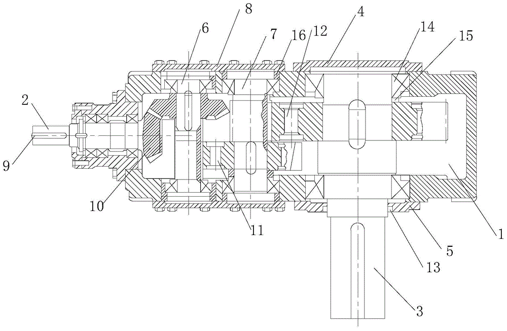
[0015] Such as figure 1 A high-power spiral bevel gear reducer shown has a body 1 and a spiral bevel gear shaft 2. The body 1 is provided with an output shaft 3, a first gear shaft 6 and a second gear shaft 7, and the output shaft 3 One end is provided with a stop cover 4, the other end is provided with a through cover 5, the two ends of the first gear shaft 6 and the second gear shaft 7 are fixed with end covers 8 by bolts, and one end of the spiral bevel gear shaft 2 is provided with a keyway 9. The other end is connected with the spiral bevel gear 10, the spiral bevel gear 10 meshes with the first gear shaft 6, the first gear shaf...


PUM


Abstract

The invention relates to a big power spiral bevel gear reducer, which is provided with an engine body and a spiral bevel gear shaft, wherein an output shaft, a first and a second gear shafts are arranged in the engine body, a stop cover is arranged on one end of the output shaft, a through cover is arranged on the other end of the output shaft, end covers are fixedly arranged on the two ends of the first and the second gear shafts through bolts, a key slot is arranged on one end of the spiral bevel gear shaft, the other end of the spiral bevel gear shaft is connected with a spiral bevel gear, the spiral bevel gear is engaged with the first gear shaft, the first gear shaft is engaged with the second gear shaft through a first gear, and the second gear shaft is engaged with the output shaft through a second gear. The big power spiral bevel gear reducer is simpler and more novel in structure, small in whole volume, large in transmission torque, small in noise, large in overload capacity, long in service life and excellent in sealing performance and dustproof performance, can not cause large damage when the power is large, has anti-loose function, and does not affect strength of a shaft.

Description

technical field [0001] The invention relates to a high-power spiral bevel gear reducer. Background technique [0002] The reducer plays the role of matching the speed and transmitting torque between the prime mover and the working machine or the actuator. The reducer is a relatively precise machine. The purpose of using it is to reduce the speed and increase the torque. It is an independent component composed of gear transmission, worm transmission, and gear-worm transmission enclosed in a rigid shell. It is often used as a reduction transmission device between the prime mover and the working machine. It plays the role of matching speed and transmitting torque, and is widely used in modern machinery. [0003] The traditional spiral bevel gear hard tooth surface reducer usually includes a box body and an input flange fixedly connected with the box body. An input shaft is arranged at the input flange, and an input gear is arranged at one end of the input shaft corresponding t...

Claims


Application Information

Patent Timeline
Patent Type & Authority Applications(China)
IPC IPC(8): F16H1/22F16H57/021F16H57/023F16H57/029
CPCF16H1/22F16H57/021F16H57/023F16H57/029F16H2057/02086
Inventor 巢惠英
Owner 常州华欣彤源电机厂
Why Eureka
Try Eureka