
Miniature calorimeter

A micro calorimeter, mass flow technology, applied in the direction of material thermal development, etc., can solve problems such as quantitative analysis of difficult materials, inability to simulate fire combustion behavior, combustion test methods that cannot fully describe combustion performance, etc., achieving low cost and easy operation. , high precision effect

Inactive Publication Date: 2015-09-09
江苏费尔曼安全科技有限公司
View PDF5 Cites 3 Cited by
  • Summary
  • Abstract
  • Description
  • Claims
  • Application Information

AI Technical Summary

Problems solved by technology

[0002] With the development of society, the increase of material wealth and population density, the frequency of fire and the damage caused by it are also increasing, and the use of flame retardant materials is one of the strategic measures to reduce and prevent fire. The flame retardant of materials has been paid more and more attention; because the combustion behavior of flame retardant materials in a fire is very complex, a single combustion test method cannot fully describe its combustion performance, so people try to test and characterize flame retardant materials The research on the method can more completely evaluate the flame retardant properties of flame retardant materials from many aspects; and the instruments currently used to measure and characterize the flame retardant properties of materials such as: oxygen index meter, horizontal / vertical combustion instrument, oxygen bomb calorimeter, etc. It cannot simulate the combustion behavior of a real fire, and many instruments for testing the flame resistance of materials can only be used for qualitative tests of flammability, flammability or non-combustibility, and it is difficult to quantitatively analyze materials

Method used


Image

  • Miniature calorimeter
  • Miniature calorimeter

Examples


Embodiment Construction

[0014] The present invention is described below in conjunction with accompanying drawing.

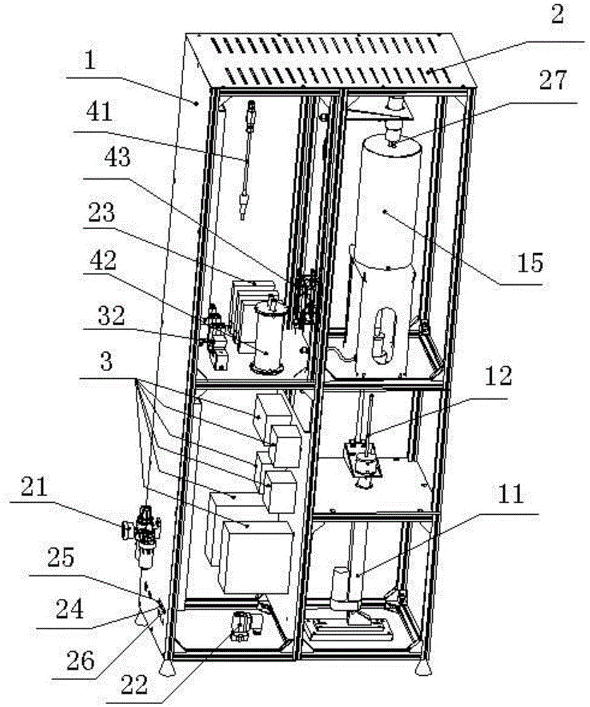
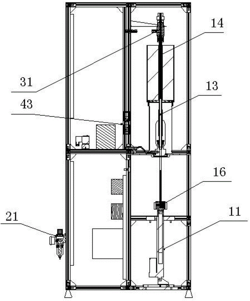
[0015] as attached Figure 1-2 As shown, a kind of miniature calorimeter described in the present invention comprises frame 1, and sample component, intake circuit, exhaust circuit and control system are arranged on frame 1, and the top of frame 1 is provided with multiple groups Heat dissipation holes 2; the sample assembly includes a sample delivery electric cylinder 11, a support rod 12, a decomposition chamber 13 and a combustion chamber 14; the decomposition chamber 13 and the combustion chamber 14 are provided with a heating furnace 15; the heating furnace 15 is divided into two One section corresponds to the decomposition chamber 13, and one section corresponds to the combustion chamber 14; the support rod 12, the decomposition chamber 13, the combustion chamber 14 and the two-stage heating furnace 15 are all provided with temperature sensors, and the temperature sensors of this ...


PUM


Abstract

The invention discloses a miniature calorimeter. The miniature calorimeter includes a frame, and the frame is provided with a sample assembly, a gas feeding loop, a gas discharge loop and a control system; the sample assembly comprises a sample feeding electric cylinder, a support bar, a decomposition chamber and a combustion chamber; the gas inlet loop comprises an oxygen channel, a nitrogen channel, an air channel, a pressure regulating valve, a solenoid valve and a mass flow controller; the combustion chamber is provided with a gas outlet, and a gas discharged through the gas outlet passes through the mass flow controller and reaches a paramagnetic oxygen concentration sensor to form a gas discharge loop; and a control system controls gas feeding, gas discharge, sample sending and feedback of detection data. Experiments of the heat release rate, the effective combustion heat, the ignition temperature and other characteristics of a material are carried out based on an oxygen consumption principle, and the combustion behaviors of the material in real fire hazard environment are well simulated, so the miniature calorimeter has the advantages of low cost, high precision, easy operation, low requirements on an experiment place, and safe and easily controlled experiment process, and is suitable for the quantitative test of the flame retardation performances of various materials.

Description

technical field [0001] The invention relates to a testing instrument for flame retardancy of materials, in particular to a miniature calorimeter with low cost, high precision, convenient operation and wide application range. Background technique [0002] With the development of society, the increase of material wealth and population density, the frequency of fire and the damage caused by it are also increasing, and the use of flame retardant materials is one of the strategic measures to reduce and prevent fire. The flame retardant of materials has been paid more and more attention; because the combustion behavior of flame retardant materials in a fire is very complex, a single combustion test method cannot fully describe its combustion performance, so people try to test and characterize flame retardant materials The research on the method can more completely evaluate the flame retardant properties of flame retardant materials from many aspects; and the instruments currently ...

Claims


Application Information

Patent Timeline
IPC IPC(8): G01N25/22
Inventor 贺名欢
Owner 江苏费尔曼安全科技有限公司
Learn More