Logic protecting emitter coupled fingerprint identification system based on constant current protection

A technology of emitter coupling and logic protection, applied in character and pattern recognition, acquisition/organization of fingerprints/palmprints, instruments, etc., can solve the problem of low recognition accuracy, and achieve the effect of simple overall structure, easy expansion, and improved efficiency.

Inactive Publication Date: 2015-09-09
CHENGDU CHUANGTU TECH
View PDF5 Cites 4 Cited by
  • Summary
  • Abstract
  • Description
  • Claims
  • Application Information

AI Technical Summary

Problems solved by technology

However, the existing fingerprint identification system is easily affected by current fluctuations, resulting in low identification accuracy

Method used


Image

  • Logic protecting emitter coupled fingerprint identification system based on constant current protection
  • Logic protecting emitter coupled fingerprint identification system based on constant current protection
  • Logic protecting emitter coupled fingerprint identification system based on constant current protection

Examples


Embodiment

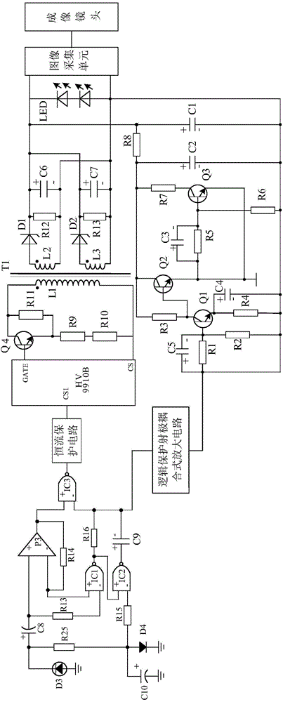
[0026] Such as figure 1 As shown, the present invention includes a fingerprint collector with a Camera communication interface and a USB communication interface, a control chip HV arranged inside the fingerprint collector, a fingerprint scanning circuit connected to the control chip HV, and an image connected to the fingerprint scanning circuit. An acquisition unit, an imaging lens connected to the image acquisition unit, an emitter-coupled asymmetric trigger circuit arranged between the connection point of the fingerprint scanning circuit and the image acquisition unit, and a beam-excited logic amplifier connected to the control chip HV circuit, a logic protection emitter-coupled amplifier circuit connected in series between the beam-excited logic amplifier circuit and the emitter-coupled asymmetric circuit, and a constant current circuit connected in series between the beam-excited logic amplifier circuit and the control chip HV protect the circuit.

[0027]The beam-excited...


PUM


Abstract

The invention discloses a logic protection emitter coupling type fingerprint recognizing system. The system mainly consists of a fingerprint collector, a control chip HV arranged in the fingerprint collector, a fingerprint scanning circuit connected with the control chip HV, an image collecting unit connected with the fingerprint scanning circuit, an imaging lens connected with the image collecting unit, and a light beam excitation type logic amplifying circuit connected with the control chip HV, wherein an emitter coupling type asymmetrical trigger circuit consists of an emitter coupling type asymmetrical circuit and a passive pi type filter circuit connected with the output terminal of the emitter coupling type asymmetrical circuit. The system disclosed by the invention is characterized in that a logic protection emitter coupling type amplifying circuit is also connected between the light beam excitation type logic amplifying circuit and the emitter coupling type asymmetrical circuit in series. According to the invention, on the basis of a traditional fingerprint recognizing system, the brand new emitter coupling type asymmetrical trigger circuit is additionally arranged, so that the defect of unstable performance existing in the traditional fingerprint recognizer can be thoroughly overcome.

Description

technical field [0001] The invention relates to a fingerprint identification system, in particular to a logic protection emitter coupling type fingerprint identification system based on constant current protection. Background technique [0002] At present, the fingerprint identification device has been widely used in people's life, which brings great convenience to people's life. However, the existing fingerprint identification system is easily affected by current fluctuations, resulting in low identification accuracy. Contents of the invention [0003] The object of the present invention is to provide a logic-protected emitter-coupled fingerprint identification system based on constant current protection for the defect that the fingerprint identification system is easily affected by current fluctuations. [0004] The present invention is realized through the following technical solutions: a logic protection emitter coupled fingerprint recognition system based on constant...

Claims


Application Information

Patent Timeline
Patent Type & Authority Applications(China)
IPC IPC(8): G06K9/00
CPCG06V40/1318
Inventor 周云扬
Owner CHENGDU CHUANGTU TECH
Why Eureka
Try Eureka