Rotor for motor of bag making machine

An electromechanical and rotor technology, applied in the field of the rotor of the bag making machine motor, can solve the problems of shortening the service life of the equipment, burning the motor, etc., and achieve the effects of reducing the mass of the rotor, saving costs, and enhancing the heat dissipation capacity

Inactive Publication Date: 2015-09-09
WUHU PINTONG PLASTIC TECH
View PDF6 Cites 2 Cited by
  • Summary
  • Abstract
  • Description
  • Claims
  • Application Information

AI Technical Summary

Problems solved by technology

In addition, during the production of plastic bags, the temperature of the working environment around the bag making machine is high, and the friction between the parts of the motor will also generate heat. If the temperature cannot be cooled or dissipated as soon as possible, it is likely to cause the motor to burn out and shorten the equipment. service life

Method used


Image

  • Rotor for motor of bag making machine
  • Rotor for motor of bag making machine

Examples


Embodiment Construction

[0025] Specific embodiments of the present invention will be described in detail below in conjunction with the accompanying drawings. It should be understood that the specific embodiments described here are only used to illustrate and explain the present invention, and are not intended to limit the present invention.

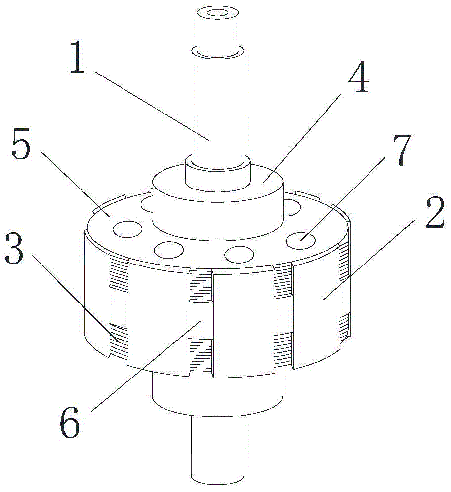
[0026] see figure 1 , the present invention provides a rotor for a bag making machine motor, comprising a rotating shaft 1, a permanent magnet 2, an inner iron core 4 and an outer iron core 5; the inner iron core 4 is set and fixed on the rotating shaft 1, and the outer iron core 5 is set It is fixed on the inner iron core 4 , and the outer iron core 5 is formed by laminating multiple silicon steel sheets 3 , the permanent magnet 2 is fixedly arranged on the outer peripheral surface of the outer iron core 5 , and a plurality of cooling holes 7 are arranged on the outer iron core 5 .

[0027] In this way, since the outer iron core 5 is formed by stacking silicon...


PUM


Abstract

The invention discloses a rotor for a motor of a bag making machine. The rotor comprises a rotating shaft (1), a permanent magnet (2), an inner iron core (4) and an outer iron core (5), wherein the inner iron core (4) sleeves and is fixed on the rotating shaft (1), the outer iron core (5) sleeves and is fixed on the inner iron core (4), the outer iron core (5) is formed by laminating silicon steel plates (3), the permanent magnet (2) is fixedly arranged on the outer peripheral face of the outer iron core (5), and a plurality of heat radiating holes (7) are arranged in the outer iron core (5). The rotor is light, uses less material, and has excellent heat radiation effect. The service lifetime of the motor of the bag making machine is prolonged.

Description

technical field [0001] The invention relates to motor parts, in particular to a rotor for a bag-making machine motor. Background technique [0002] The bag making machine is a machine for making various plastic packaging bags or other material packaging bags. It can process various plastic or other material packaging bags with different sizes, thicknesses and specifications. Generally, plastic packaging bags are the main products. [0003] The rotor of the bag making machine motor is composed of laminations, rotor shaft and windings. When the motor is working, the internal temperature of the motor increases, which intensifies the temperature rise of the rotor, which directly affects the conversion rate of energy consumption. In addition, during the production of plastic bags, the temperature of the working environment around the bag making machine is high, and the friction between the parts of the motor will also generate heat. If the temperature cannot be cooled or dissipat...

Claims


Application Information

Patent Timeline
Patent Type & Authority Applications(China)
IPC IPC(8): H02K1/27H02K1/32
Inventor 陈可夏
Owner WUHU PINTONG PLASTIC TECH
Why Eureka
Try Eureka