Micro motor fully automatic packaging machine

A fully automatic packaging machine and micro-motor technology, which is applied in the direction of electromechanical devices, electric components, and manufacturing motor generators, etc. It can solve the problems that micro-motors are difficult to achieve fully automatic assembly, micro-motors are unqualified, and cannot be tightly held.

Active Publication Date: 2015-09-09
GUANGDONG CHAOLI MOTOR CO LTD
View PDF4 Cites 5 Cited by
  • Summary
  • Abstract
  • Description
  • Claims
  • Application Information

AI Technical Summary

Problems solved by technology

Therefore, when the micro-motor is packaged, it is necessary to accurately align the end cover and the housing, which is also an important reason why the micro-motor package has not been able to achieve full automation.
[0007] Another important reason that makes it difficult to realize fully automatic assembly of micro-motors is that after the housing, rotor and end cover are installed, the two brushes on the end cover must closely and directly cooperate with the commutator on the rotating shaft, that is, two The brushes must be able to hold the commutator tightly. In

Method used


Image

  • Micro motor fully automatic packaging machine
  • Micro motor fully automatic packaging machine
  • Micro motor fully automatic packaging machine

Examples


Embodiment Construction

[0036] Further description will be given below in conjunction with the accompanying drawings and preferred embodiments of the present invention.

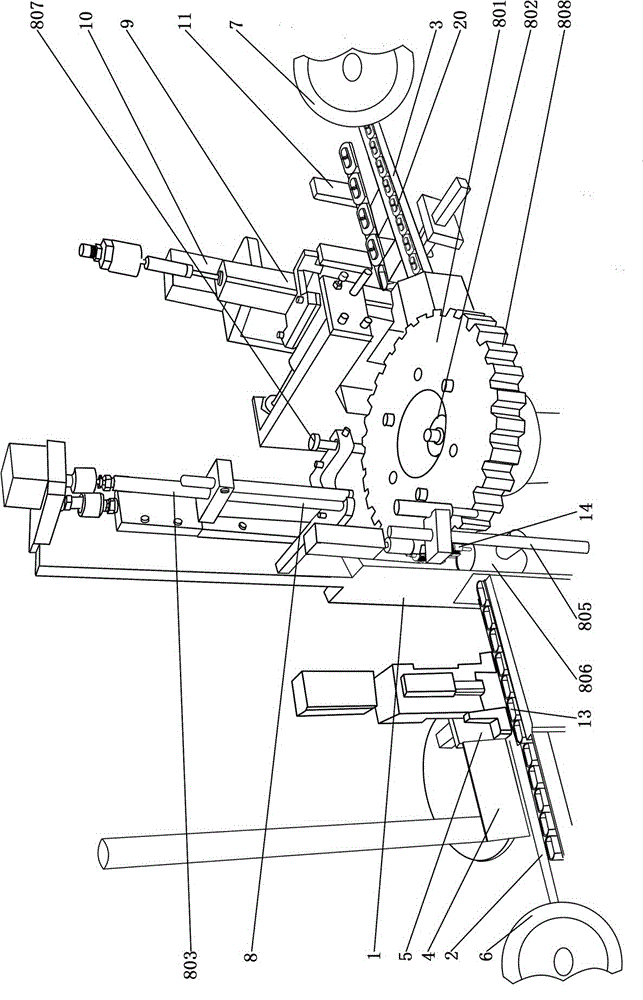
[0037] like figure 1 As shown, this micro-motor automatic packaging machine includes a frame 1, and a shell guide rail 2, an end cover guide rail 3, a shell push mechanism 4, a shell detection and rectification device 5, and a shell finishing shock plate arranged on the frame 1. 6. End cover finishing oscillating disk 7, rotor and casing assembly device 8, end cover assembly device 9, riveting device 10 and finished product exit mechanism 11; the output port of casing finishing oscillating disk 6 is connected with the starting end of casing guide rail 2; the casing is pushed The mechanism is set at the starting end of the shell guide rail 2; the rotor and shell assembly device 8 is set in the middle of the shell guide rail 2; the shell detection and rectification device 5 is set between the shell propulsion mechanism 4, the rotor an...


PUM


Abstract

The invention relates to a micro motor fully automatic packaging machine. The micro motor fully automatic packaging machine includes a rack, a shell guide rail, a turntable, a steeping driving device and a rotor pushing and pressing mechanism; a plurality of magnetic attraction grooves of which the section is half round are distributed on the turntable along the circumferential direction of the turntable at equal intervals; and the rotor pushing and pressing mechanism includes a push-in lifting mechanism, a rotor pushing rod, an adapting lifting mechanism, an adapting lifting seat, an adapting bottom plate, an adapting fixed clamping sheet, an adapting movable clamping sheet and an adapting air cylinder. Since the adapting movable clamping sheet and the adapting fixed clamping sheet are adopted to form a guide cylinder to perform adapting transition, and therefore, the problem of difficulty in realizing accurate alignment of the magnetic attraction grooves on the turntable and the shell guide rail can be solved; a rotor is constantly limited by the guide cylinder, so that a transient suspension state of the rotor in a push-in process can be avoided, and therefore, the constant stability of the rotor can be ensured in the push-in process, and accurate alignment of the rotor and a shell can be ensured; the lower end of the rotation shaft of the rotor can be accurately inserted into a shaft hole at the lower end of the shell, so that fully automatic production of the packaging of micro motors can be realized.

Description

technical field [0001] The invention relates to a micro-motor production equipment, in particular to a micro-motor automatic packaging machine. Background technique [0002] Micro motors are commonly used driving devices, and generally use batteries for DC power supply. [0003] The micromotor generally includes a casing, a rotor and an end cover. The lower end of the casing is provided with a shaft hole, and two magnetic pieces with opposite polarities are arranged in the casing. The rotor includes a rotating shaft, a coil winding, a windmill piece and a commutator. The coil winding is installed on In the middle of the rotating shaft, the windmill blade is installed at the lower end of the rotating shaft, and the commutator is installed at the upper end of the rotating shaft. Two power connectors are arranged outside the end cover, and two electric brushes connected with the power connector are arranged on the inner surface of the end cover. [0004] When assembling the mi...

Claims


Application Information

Patent Timeline
IPC IPC(8): H02K15/00
Inventor 张彦志陈祉浩蔡章锦杨壮凌
Owner GUANGDONG CHAOLI MOTOR CO LTD
Why Eureka
Try Eureka