Antenna selection and power distribution method based on energy efficiency

A technology of antenna selection and allocation method, applied in wireless communication, energy consumption reduction, advanced technology and other directions, can solve the problems of increasing response time, low energy efficiency value, unable to meet the needs of online users, etc.

Inactive Publication Date: 2015-09-09
INNER MONGOLIA UNIVERSITY
View PDF3 Cites 8 Cited by
  • Summary
  • Abstract
  • Description
  • Claims
  • Application Information

AI Technical Summary

Problems solved by technology

However, the energy efficiency values ​​of these methods are always lower than the energy efficiency value of the group method, and the combination search of antenna selection and power allocation needs many iterations to determine the optimal combination
When there are many distributed antennas in the distributed antenna system, the combined search scheme will generate additional circuit energy consumption due to its high complexity, which will offset the transmission energy saved by it, and the high complexity will also increase the response time , unable to meet the needs of online users

Method used


Image

  • Antenna selection and power distribution method based on energy efficiency
  • Antenna selection and power distribution method based on energy efficiency
  • Antenna selection and power distribution method based on energy efficiency

Examples


Embodiment Construction

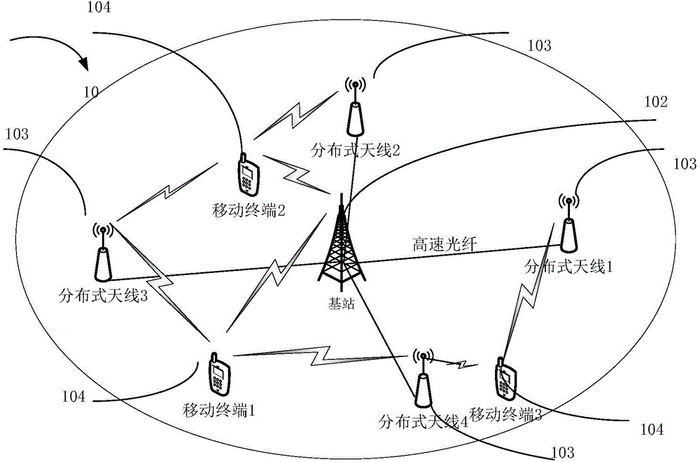
[0050] like figure 1 As shown, the distributed antenna system 10 includes: a base station 102, a distributed antenna unit 103, and a mobile terminal 104; the number of the base station 102 is 1, which is used to complete the centralized processing of data, and the base station 102 includes 4 antennas, But the base station 102 is not limited to include 4 antennas; the number of the distributed antenna units 103 is 4, but not limited to 4, and each distributed antenna unit 103 has 1 antenna, but not limited to only 1 An antenna; the number of mobile terminals 104 is 3, but not limited to 3, and the mobile terminal 104 has 1 antenna, but is not limited to only 1 antenna.

[0051] The distributed antenna unit 103 is distributed on the edge of the cell, connected to the base station 102 through a high-speed broadband optical fiber, and jointly constitutes the transmitting end of the system, and the transmitting antenna is the antenna of the transmitting end, and its number N t =8....


PUM


Abstract

The invention provides an antenna selection and power distribution method based on energy efficiency. The method comprises the steps as follows: step S1) obtaining channel state information transmitted by each mobile terminal; step S2) ordering channel conditions of all transmitting antennas according to good and bad conditions in accordance with the channel state information, transmitting the front Ntt transmitting antennas to form a transmitting antenna set; calculating energy efficiency optimal value of all transmitting antenna combinations in the transmitting antenna set (img file is equal to DDA0000697273720000011. TIF wi is equal to 86 and he is equal to 78), wherein the corresponding antenna combination thereof is (img file is equal to DDA0000697273720000012. TIF wi is equal to 76 and he is equal to 76); then selecting the front Ntt adds 1 transmitting antennas to form the transmitting antenna set, calculating (img file is equal to DDA0000697273720000013. TIF wi is equal to 112 and he is equal to 85), wherein the (img file is equal to DDA0000697273720000015. TIF wi is equal to 68 and he is equal to 78) is an optimal antenna combination if (img file is equal to DDA0000697273720000014. TIF wi is equal to 238 and he is equal to 83), otherwise enabling Ntt to be equal to Ntt adds 1, and repeating the above processes until the antennas in the transmitting antenna set are all transmitting antennas; step S3) performing transmitting power distribution to the transmitting antennas in the optimal antenna combination by using secondary allocation. The method of the invention effectively avoids energy surplus of the mobile terminal, achieves maximum usage of whole system energy, and greatly reduces algorithm complexity in comparison with existing method.

Description

technical field [0001] The invention relates to the field of wireless resource management in a distributed mobile communication system, in particular to an antenna selection and power distribution method based on energy efficiency. Background technique [0002] With the continuous increase of energy demand and energy price, and the continuous aggravation of environmental problems, how to improve the energy efficiency of communication networks and realize green communication has been extensively studied and discussed. As the core of the centralized antenna system, the base station needs to consume a lot of energy in order to achieve reliable communication with edge users and ensure full coverage of users. In order to make the transmitting antenna of the base station as close as possible to the user and improve the energy utilization rate, a distributed antenna system composed of geographically separated antenna units connected by optical fiber came into being; it can not only...

Claims


Application Information

Patent Timeline
Patent Type & Authority Applications(China)
IPC IPC(8): H04W72/04
CPCH04W72/0473Y02D30/70
Inventor 孙锴安凯月黄威贾美俊张磊
Owner INNER MONGOLIA UNIVERSITY
Why Eureka
Try Eureka