
Printing and dyeing wastewater treatment device

A technology for treating equipment and printing and dyeing wastewater, applied in the fields of filtration and separation, separation methods, chemical instruments and methods, etc., can solve the problems of discount of precipitation treatment effect, long precipitation time, difficult to clean, etc., to achieve good pretreatment effect and environmental requirements Low, small footprint effect

Active Publication Date: 2015-09-16
苏州盛泽科技创业园发展有限公司
View PDF5 Cites 9 Cited by
  • Summary
  • Abstract
  • Description
  • Claims
  • Application Information

AI Technical Summary

Problems solved by technology

The sedimentation method can only target the impurities that are easy to sink, and the sedimentation tank takes up a lot of space and takes a long time to settle. When the next step is processed, the impurities at the bottom of the tank are easily stirred during the transfer of printing and dyeing wastewater, which greatly reduces the effect of the previous sedimentation treatment.
The filtration method is based on the fiber length and particle size in the printing and dyeing wastewater, and selects a suitable mesh to filter the printing and dyeing wastewater. Simply filter the printing and dyeing wastewater through the gauze, which is easy to cause blockage to the filter. In order to ensure the flow, To reduce the impact of clogging on the flow rate, the area of ​​the filter screen is often made very large, which not only takes up space, but also the filtered fibers and particles are scattered and difficult to clean

Method used


Image

  • Printing and dyeing wastewater treatment device
  • Printing and dyeing wastewater treatment device
  • Printing and dyeing wastewater treatment device

Examples


Embodiment approach 1

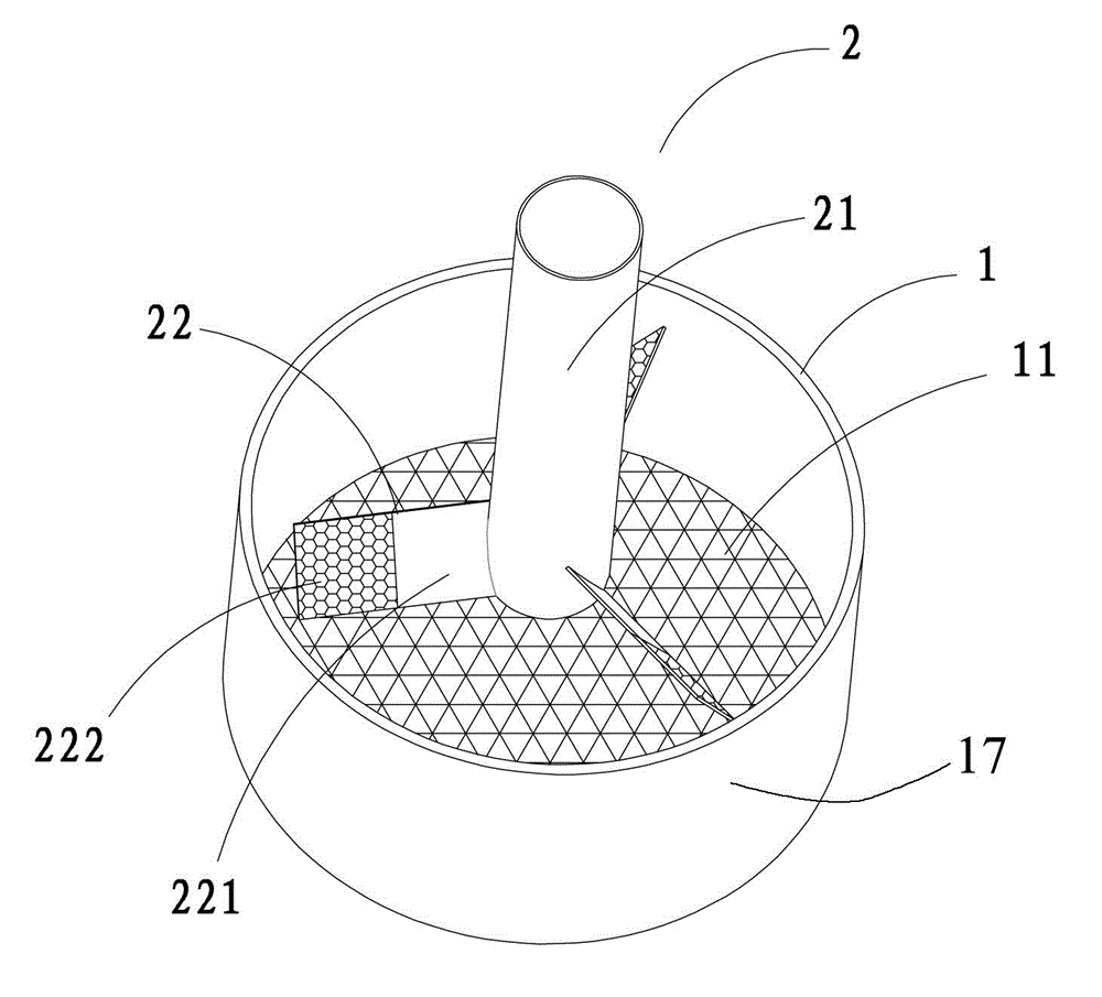
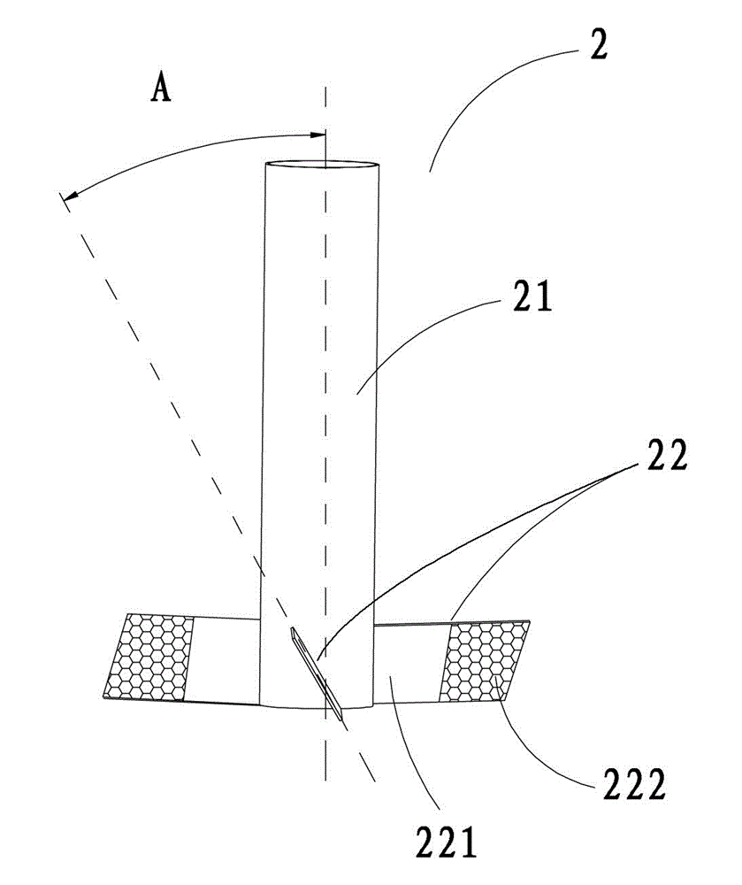
[0027] Such as figure 1 and 2 As shown, a kind of printing and dyeing wastewater treatment equipment includes a water filter tank 1 and a rotary filter mechanism 2, the bottom of the filter water tank 1 is provided with a bottom filter screen 11, and the rotary filter mechanism 2 includes a rotating shaft 21 and is fixedly connected to the The centrifugal filter blade 22 on the rotating shaft 21, the centrifugal filter blade 22 includes a solid sheet area 221 and a filter screen area 222, and the solid sheet area 221 is arranged on an end where the centrifugal filter blade 22 is connected to the rotating shaft 21, The filter screen area 222 is disposed at the end of the centrifugal filter blade 22 . The centrifugal filter blade 22 is arranged obliquely relative to the axial direction of the rotating shaft 21, and the angle A between the centrifugal filtering blade 22 and the rotating shaft 21 is 40°, that is, in the working state, the rotating shaft 21 It is arranged vertic...

Embodiment approach 2

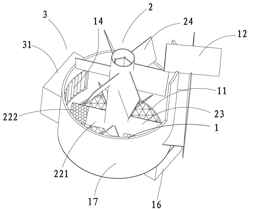
[0030] Such as Figures 3 to 7 As shown, a kind of printing and dyeing wastewater treatment equipment includes a water filter tank 1 and a rotary filter mechanism 2, the bottom of the filter water tank 1 is provided with a bottom filter screen 11, and the rotary filter mechanism 2 includes a rotating shaft 21 and is fixedly connected to the The centrifugal filter blade 22 on the rotating shaft 21, the centrifugal filter blade 22 includes a solid sheet area 221 and a filter screen area 222, and the solid sheet area 221 is arranged on an end where the centrifugal filter blade 22 is connected to the rotating shaft 21, The filter screen area 222 is disposed at the end of the centrifugal filter blade 22 . The centrifugal filter blade 22 is arranged obliquely relative to the axial direction of the rotating shaft 21, and the angle A between the centrifugal filtering blade 22 and the rotating shaft 21 is 40°, that is, in the working state, the rotating shaft 21 Set vertically to the...


PUM


Abstract

The invention belongs to the technical field of printing and dyeing wastewater treatment, in particular to a printing and dyeing wastewater treatment device which comprises a water filtering tank and a rotary filtering mechanism. A tank bottom filter screen is arranged at the bottom of the water filtering tank, the rotary filtering mechanism comprises a rotating shaft and centrifugal filter screen blades fixedly connected onto the rotating shaft, each centrifugal filter screen blade includes a solid blade area and a filter screen area, the solid blade area is arranged at one end of each centrifugal filter screen blade connected with the rotating shaft, and the filter screen area is arranged at the tail end of each centrifugal filter screen blade. The printing and dyeing wastewater treatment device is compact in structure, space occupancy is decreased, blocking of the filter screen can be avoided, and printing and dyeing wastewater can be efficiently pretreated.

Description

technical field [0001] The invention belongs to the technical field of printing and dyeing wastewater treatment, and in particular relates to a printing and dyeing wastewater treatment equipment. Background technique [0002] Printing and dyeing wastewater is the most polluting wastewater produced by the textile industry. Its discharge accounts for more than 10% of the total industrial wastewater discharge. It is one of the most important sources of water pollution. The comprehensive treatment of printing and dyeing wastewater is an urgent problem to be solved. [0003] At present, the treatment of printing and dyeing wastewater has formed a typical treatment process, which can be summarized into three levels of treatment: the first level of treatment is the pretreatment of printing and dyeing wastewater, mainly to remove larger fibers and particles in printing and dyeing wastewater; the second level of treatment can remove printing and dyeing wastewater Most of the pollut...

Claims


Application Information

Patent Timeline
Patent Type & Authority Applications(China)
IPC IPC(8): B01D36/00
Inventor 赖柱伟
Owner 苏州盛泽科技创业园发展有限公司
Learn More