
Processing method for diesel oil engine piston rod deep hole

A processing method and piston rod technology, applied in the direction of pistons, metal processing equipment, mechanical equipment, etc., can solve the problems of low processing efficiency, low cutting parameters, and affecting high-precision processing, and achieve scientific and reasonable cutting sequence and scientific and reasonable arrangement , Guarantee the effect of processing quality

Active Publication Date: 2015-09-16
CSSC MES DIESEL
View PDF6 Cites 2 Cited by
  • Summary
  • Abstract
  • Description
  • Claims
  • Application Information

AI Technical Summary

Problems solved by technology

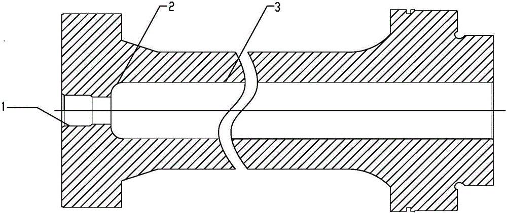
[0002] In large diesel engines, the piston rod with the deep bore is usually forged, see figure 1 , the function of the deep hole 3 is oil cooling, although the size requirements are not high, but the problems existing in the processing of the deep hole 3 will affect the high-precision processing of the subsequent process
The depth of the deep hole 3 of the piston rod is usually more than 30 times the diameter of the hole, so the length of the processing is longer, and it is easy to be deflected during drilling. In addition, factors such as unsatisfactory chip removal conditions also lead to low processing efficiency; The arc 2 at the bottom of hole 3 is usually processed on a lathe with a back boring tool, but due to the overhang of the tool, the cutting parameters are very low, the production efficiency is low, and the deformation of the workpiece leads to inconsistent calibration standards, so the bottom circle often occurs. The arc 2 and the deep hole 3 have a big connection problem, so it takes a lot of time to polish

Method used


Image

  • Processing method for diesel oil engine piston rod deep hole
  • Processing method for diesel oil engine piston rod deep hole
  • Processing method for diesel oil engine piston rod deep hole

Examples


Embodiment Construction

[0030] The present invention will be described in detail below in conjunction with the accompanying drawings and specific embodiments, so that the advantages and features of the present invention can be more easily understood by those skilled in the art, but the protection scope of the present invention cannot be limited thereby.

[0031] Taking the processing of a diesel engine piston rod with an outer diameter of Φ310 and a length of 4695mm as an example, the diameter of the processed deep hole 2 is Φ150, the length of the deep hole 2 is 4549mm, and the radius of the arc 3 at the bottom of the deep hole 2 is R32 , requiring straightness <0.2mm, the specific processing process is as follows:

[0032] In order to obtain the best straightness, the workpiece is rotated, the tool is rotated in the opposite direction, and the feeding motion is used during processing.

[0033] Step 1, rough drill the inner hole

[0034] The tool uses an ejector drill, see image 3 , the ejector d...


PUM

PropertyMeasurementUnit
lengthaaaaaaaaaa
lengthaaaaaaaaaa
depthaaaaaaaaaa

Abstract

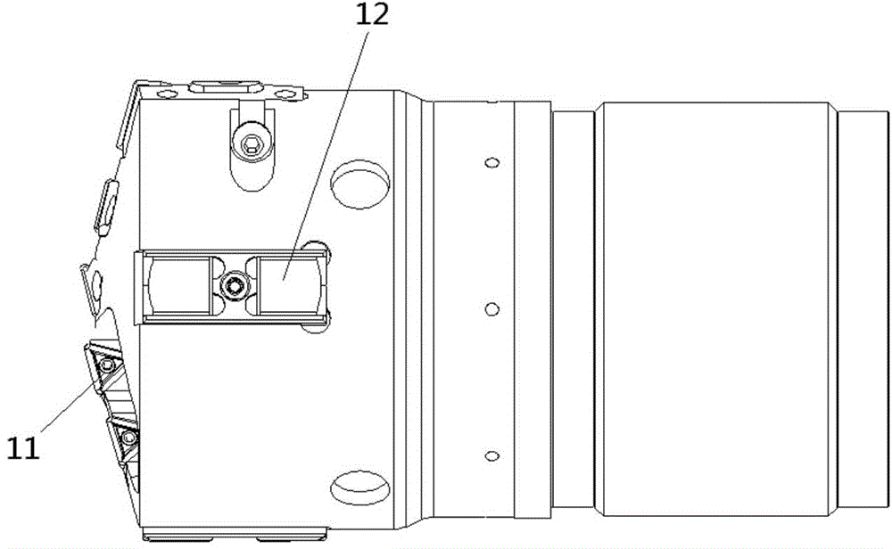
A processing method for a diesel oil engine piston rod deep hole comprises steps of an inner hole rough drilling step, an inner hole accurate expanding step, a bottom arc rough processing step, a bottom arc fine processing step and a detection step. During drilling process for the deep hole, a work piece rotationally moves, a cutter rotationally moves and conducts feeding motions in an opposite direction; the cutters employs a specific-made serial ejector drill; with the negative pressure produced by the cutter, cutting chips can be easily discharged out and cutter retraction for chip discharging can be avoided; and the cutter is supported by a guide block on a cutter body to balance cutting force during drilling. By the use of the processing method for the diesel oil engine piston rod deep hole, linearity of the deep hole is increased and a problem of large cutter contact between the deep hole bottom arc and the deep hole is solved, so stable product quality and high cutting efficiency can be achieved; and the processing method is suitable for processing deep holes of a large diesel oil engine piston rod, in particular for processing of a deep hole having a large round arc on the bottom and with an aperture 30 times larger than normal deep holes.

Description

technical field [0001] The invention relates to a processing technology for a large diesel engine accessory, in particular to a processing method for a deep hole of a piston rod of a diesel engine, and belongs to the technical field of mechanical processing. Background technique [0002] In large diesel engines, the piston rod with the deep bore is usually forged, see figure 1 , the function of the deep hole 3 is oil cooling, although the size requirements are not high, but the problems existing in the processing of the deep hole 3 will affect the high-precision processing of the subsequent process. The depth of the deep hole 3 of the piston rod is usually more than 30 times the diameter of the hole, so the length of the processing is longer, and it is easy to be deflected during drilling. In addition, factors such as unsatisfactory chip removal conditions also lead to low processing efficiency; The arc 2 at the bottom of hole 3 is usually processed on a lathe with a back b...

Claims


Application Information

Patent Timeline
Patent Type & Authority Applications(China)
IPC IPC(8): B23B35/00B23B41/02
CPCB23B35/00B23B41/02B23B2215/245
Inventor 杨勇陈琦刘九斤
Owner CSSC MES DIESEL
Learn More