Method and device for improving efficiency in engraving three-dimensional images in large-area flat glass

A technology of flat glass and three-dimensional images, which is applied in the field of optics, can solve problems affecting the efficiency of engraving processing, etc., and achieve the effect of improving engraving speed and efficiency, improving efficiency, and improving engraving efficiency

Active Publication Date: 2015-09-16
ZHEJIANG HOLY LASER TECH CO LTD
View PDF7 Cites 16 Cited by
  • Summary
  • Abstract
  • Description
  • Claims
  • Application Information

AI Technical Summary

Problems solved by technology

However, in the engraving process of the existing technology, only relying on one machine head, that is, one high-speed galvanometer system, it often ...

Method used


Image

  • Method and device for improving efficiency in engraving three-dimensional images in large-area flat glass
  • Method and device for improving efficiency in engraving three-dimensional images in large-area flat glass
  • Method and device for improving efficiency in engraving three-dimensional images in large-area flat glass

Examples


Embodiment

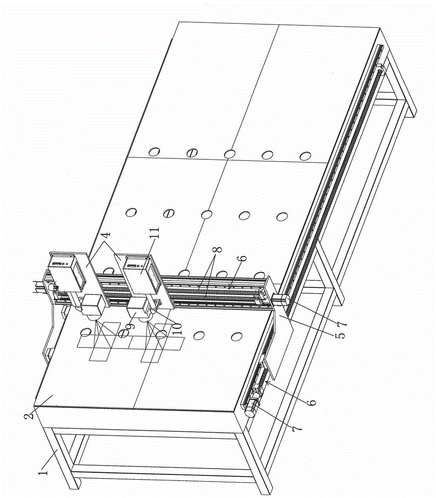
[0033] Embodiment: A method for improving the efficiency of engraving three-dimensional images in large-area flat glass, including a process of using laser focusing to form microburst points in the flat glass, and also including a process of moving the laser focus point in the flat glass, Wherein, before the laser forms the first microburst point in the flat glass, the image is first divided into at least two areas, preferably two areas, each area is correspondingly provided with a high-speed galvanometer, and then each area is respectively set Determine the displacement path range of the corresponding high-speed galvanometer; in the process of setting the displacement path range of the high-speed galvanometer, each area is divided into at least two parallel engraving partitions, and the high-speed galvanometer is between each other On the premise that there is no collision between them, the image carving of each area is completed separately.

[0034] Furthermore, the coordina...

Embodiment 2

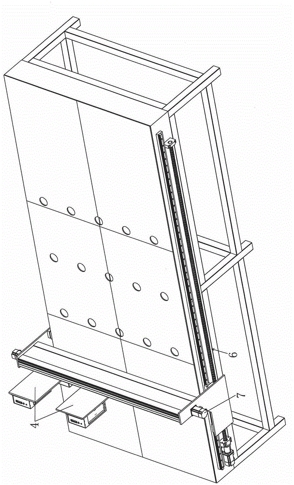
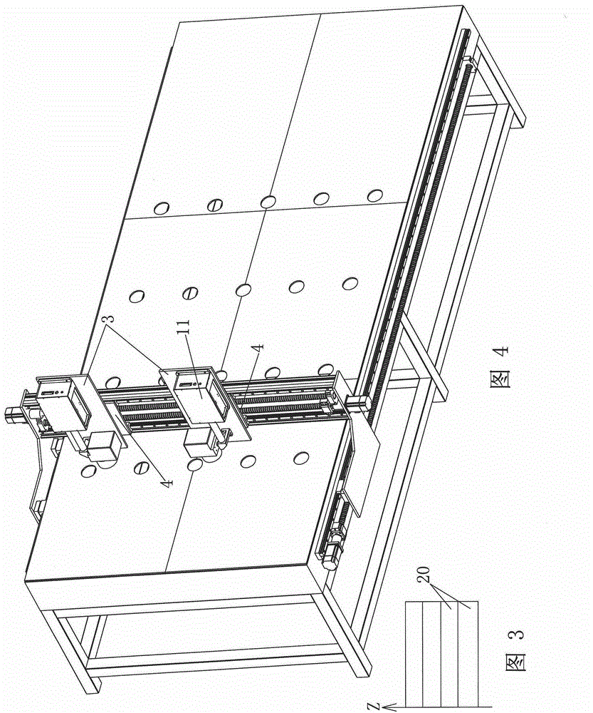
[0045] Embodiment 2: The difference between this embodiment and Embodiment 1 is that, as Figure 4 As shown, it also includes two Z-direction mobile stations 3, each Z-direction mobile station 3 is correspondingly connected to an X-direction mobile station 4, and the high-speed vibrating mirror system is arranged on the Z-direction mobile station 3; The screw nut pairs and servo motors (not shown) connected to the platform 3 are all arranged on the X-direction mobile platform 4. In the high-speed galvanometer system, the emission direction of the laser source 11 is parallel to the motion track of the Z-direction mobile platform 3 .

[0046] When the three-dimensional pattern is too thick, such as image 3 As shown, the area to be engraved is divided into at least two layers of parallel engraving blocks 20 in the direction of the Z axis. One layer engraves the engraving partitions in the X-Y axis direction of this layer until the engraving of each layered block in the Z-axis d...


PUM


Abstract

The invention discloses a method and a device for improving efficiency in engraving three-dimensional images in large-area flat glass. The method includes: adopting more than two high-speed galvanometers to deflect more than two branches of laser to control positions of laser focusing points; forming micro-explosion points inside the flat glass to acquire the three-dimensional images inside and outside the glass. The device based on the method comprises a support, a glass placement platform, a movable positioning mechanism and high-speed galvanometer systems, the glass placement platform is arranged in the support, the movable positioning mechanism comprises at least two X-direction moving platforms and one Y-direction moving platform, the X-direction moving platforms are connected with the Y-direction moving platform, the movable positioning mechanism is connected with the support and positioned above the glass placement platform, and the high-speed galvanometer systems are arranged on the X-direction moving platforms. The high-speed galvanometer systems are adopted for image engraving of the flat glass at the same time, so that engraving efficiency can be improved substantially.

Description

technical field [0001] The invention relates to the field of optical technology, in particular to a laser energy-concentrating processing device, in particular to a method and device for improving the efficiency of engraving three-dimensional images in large-area flat glass. Background technique [0002] In the prior art, lasers are often used to carry out high-precision engraving at any position inside large-format flat glass; since laser engraving on transparent objects is achieved by using lasers to generate micro-burst points in transparent objects, the large-format flat glass Thousands of microbursts are generated during the glass engraving process. However, in the engraving process of the prior art, relying on only one machine head, that is, one high-speed galvanometer system, it often takes several hours or even tens of hours to complete engraving on a large-format flat glass, which obviously affects the engraving process efficiency. Contents of the invention [00...

Claims


Application Information

Patent Timeline
IPC IPC(8): B23K26/362B23K26/08B23K26/064B23K26/06B23K26/402B23K101/18
CPCB23K26/06B23K26/0665B23K26/083B23K26/0884B23K2101/18
Inventor 卢巍胡志刚
Owner ZHEJIANG HOLY LASER TECH CO LTD
Why Eureka
Try Eureka