Transmission gear of electric steel wire cutter

A transmission device and steel wire technology, which is applied in metal processing and other directions, can solve the problems of unfavorable family popularization, cumbersome use process, complex and heavy structure, etc., and achieve the effect of simple and compact structure, convenient operation and simple principle

Inactive Publication Date: 2015-09-16
安庆旭东工贸有限责任公司
View PDF10 Cites 4 Cited by
  • Summary
  • Abstract
  • Description
  • Claims
  • Application Information

AI Technical Summary

Problems solved by technology

[0004] Aiming at the problems in the prior art that the structure of the household electric wire cutter device is too complicated and bulky, the use process is cumbersome, the cost is relatively expensive, and it is not conducive to the popularization of the family, the present invention provides a transmission device for the electric wire cutter, which has a simple and compact structure and a simple principle , easy to operate, low cost, and conducive to the popularization and use of ordinary families

Method used


Image

  • Transmission gear of electric steel wire cutter
  • Transmission gear of electric steel wire cutter
  • Transmission gear of electric steel wire cutter

Examples


Embodiment Construction

[0015] In order to make the technical means, creative features, goals and effects achieved by the present invention easy to understand, the present invention will be further described below in conjunction with specific illustrations.

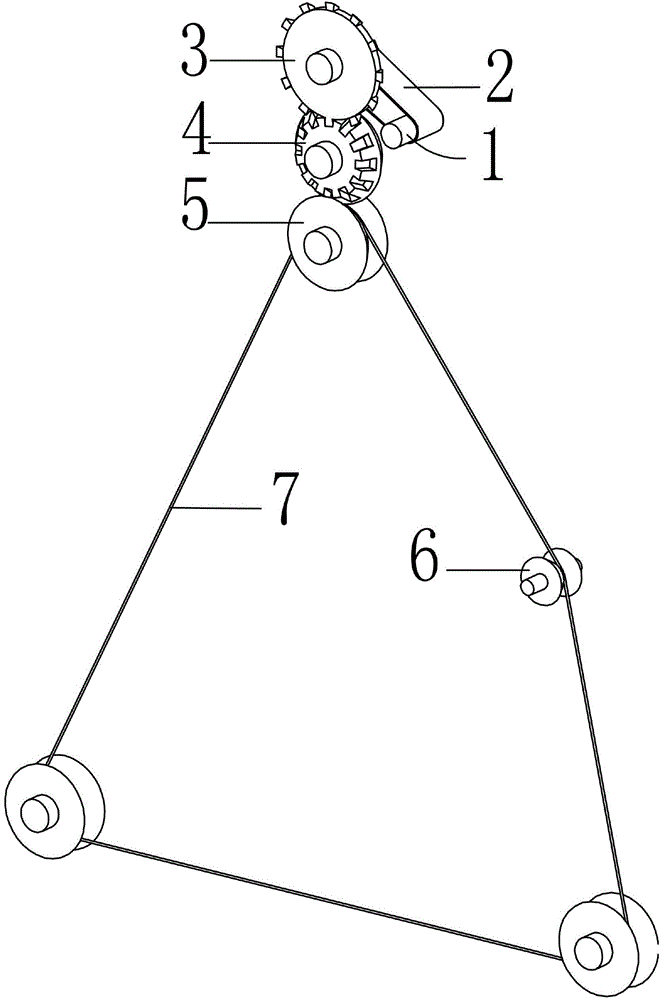
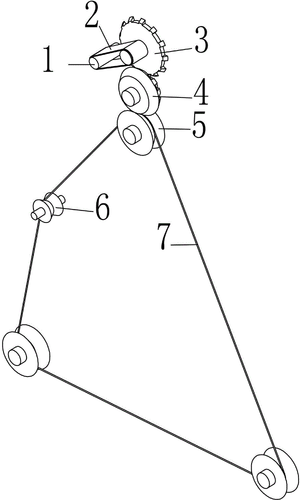
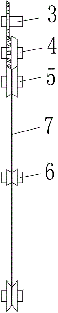
[0016] Such as figure 1 , figure 2 and image 3 As shown, a transmission device of an electric wire cutter in this embodiment, a transmission device of an electric wire cutter, includes a drive shaft 1, a transmission belt 2, a bevel gear 3, a V-shaped transmission wheel 4, a positioning transmission wheel 5, a tightening Transmission wheel 6 and steel wire 7, described bevel gear 3 is positioned at the top left of driving shaft 1, one end of bevel gear 2 is connected with driving shaft 1 through transmission belt 2, the other end of bevel gear 3 meshes with V-shaped transmission wheel 4, and driving shaft 1 Connected with the motor to make the whole device run, the bevel gear 2 is used to drive the V-shaped transmission wheel 4 to move; the ...


PUM


Abstract

The invention relates to the field of kitchen appliance, in particular to a transmission gear of an electric steel wire cutter. The transmission gear comprises a driving shaft, a transmission belt, a bevel gear, a V-shaped transmission wheel, three locating transmission wheels, a fastening transmission wheel and a steel wire. The bevel gear is located on the upper left portion of the driving shaft, one end of the bevel gear is connected with the driving shaft through the transmission belt, and the other end of the bevel gear is meshed with the V-shaped transmission wheel. The V-shaped transmission wheel is located under the bevel gear, and the side face of the V-shaped transmission wheel is in the shape of a V-shaped protrusion and attached to the side faces of the locating transmission wheels. The steel wire is clamped between the side face of the V-shaped transmission wheel and the side faces of the locating transmission wheels. The V-shaped transmission wheel is matched with the bevel gear. The three locating transmission wheels are not located on the same straight line, the side faces of the locating transmission wheels are in a concave V shape, and the steel wire is wound around the middle portions of the locating transmission wheels. The fastening transmission wheel is located on the right side of the middle portion between the upper locating transmission wheel and the right locating transmission wheel. The steel wire is wound around the middle of the side face of the fastening transmission wheel, and the fastening transmission wheel is used for controlling the tightness degree of the steel wire. The steel wire is in a closed ring shape. The transmission gear is simple in structure, small, exquisite, simple in principle, convenient to operate, low in manufacturing cost, and capable of being used and popularized among ordinary families.

Description

technical field [0001] The invention relates to the field of kitchen appliances, in particular to a transmission device for electric wire cutters. Background technique [0002] With the advancement of modern science and technology and the improvement of people's living standards, household kitchen work is becoming more and more automated and intelligent. All kinds of small kitchen appliances that replace people's manual operations have emerged as the times require. However, in the current kitchen life, the cutting work of food remains at the original level, and is still completed by people's manual operation of knives. In view of this, there is an urgent need for a small household electrical appliance that is convenient for people to quickly and safely cut vegetables, fruits, meat and other foods in ordinary families in daily life. [0003] It is known in the prior art that household electric wire cutters have been designed to solve the above problems. Chinese patent appli...

Claims


Application Information

Patent Timeline
IPC IPC(8): B26D5/08B26D1/547
Inventor 童旭东
Owner 安庆旭东工贸有限责任公司
Why Eureka
Try Eureka