
Special cutting machine for floor open joint repair batten

A cutting machine and seam separation technology, applied in the manufacture of thin wood chips, wood processing equipment, manufacturing tools, etc., can solve the problems of narrow width, difficult wood strips, easy to break, etc., and achieve simple structure, convenient operation, and low cost Effect

Inactive Publication Date: 2015-09-16
SIYANG SHUNYANG WOOD
View PDF0 Cites 2 Cited by
  • Summary
  • Abstract
  • Description
  • Claims
  • Application Information

AI Technical Summary

Problems solved by technology

The panel of the solid wood composite floor is formed by laminating multiple layers of veneer, and then attached to the surface of the substrate. In order to meet the size requirements of different customers, the panel is first laminated to form a large-area whole board, and then the whole board is cut into strips The veneer used to make the panel is very thin and easy to break. In the process of processing, several small veneers are often glued and spliced ​​to form a large veneer as a layer of the panel. This spliced ​​veneer is used as the outermost panel. There are often gaps after hot pressing, and the gaps need to be repaired in the subsequent process. The material difference between gypsum and veneer makes it difficult to repair with gypsum alone. Cutting the veneer of the panel into wooden strips for repair can obtain the best results. However, the width of the wood strips used is very narrow, and its strength is greatly affected by the natural texture. It is difficult to obtain the required wood strips by manual cutting. At present, there is no special method for cutting veneers to obtain the required wood. strip of equipment

Method used


Image

  • Special cutting machine for floor open joint repair batten

Examples


Embodiment Construction

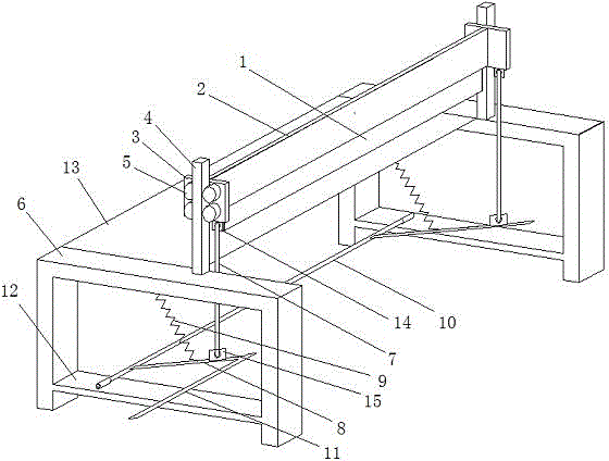
[0012] Such as figure 1 The shown special cutting machine for repairing wooden strips from the floor includes a cutter 1 and a platform 13 with brackets 6 on both sides. There are two positioning plates 3, and the two positioning plates 3 are respectively provided with two rows of guide wheels 5 on one side facing the outside of the platform 13, and guide rods 4 are slidably connected between the two rows of guide wheels 5, and the guide rods 4 are vertically connected respectively. Fixed directly on the brackets 6 on both sides of the platform 13; the cutter 1 is parallel to the end of the platform 13, and the side of the cutter 1 facing the platform 13 coincides with the plane where the end of the platform 13 is located; A driving rod 8 is connected, and one end of the driving rod 8 is fixedly connected to the rotating shaft 10 on the beam 12 of the bracket 6 below the platform 13, the rotating shaft 10 is parallel to the end of the platform 13, and the driving rod 8 is prov...


PUM


Abstract

The invention discloses a special cutting machine for a floor open joint repair batten. The machine comprises a cutter, and a platform provided with brackets at the two sides, wherein an edge of the cutter is downwards fixed on a cutter post; the two ends of the cutter post are respectively in sliding connection to two guide rods; the two guide rods are respectively and vertically fixed on the brackets at the two sides of the platform; the cutter is parallel to the end part of the platform, and one surface, towards the platform, of the cutter is overlapped with a plane of the end part of the platform; the cutter post is connected with a driving rod through a connecting rod; one end of the driving rod is rotationally connected to the brackets; and the two sides of the connected place between the driving rod and the connecting rod are respectively connected with a return spring and a pedal rod. The machine has the advantages of time and labor saving, high efficiency, simple structure, convenience for operation and low manufacturing cost.

Description

technical field [0001] The invention relates to the field of floor manufacturing equipment, in particular to a special cutting machine for floor seam repair wooden strips. Background technique [0002] With the development of the economy and the progress of the society, more and more wooden floorings appear in the home decoration with the characteristics of beautiful appearance, close to nature, warm in winter and cool in summer, and its varieties and patterns are various. Solid wood composite flooring is a type of floor derived from solid wood flooring. It overcomes the disadvantage of unidirectional isotropy of solid wood flooring. It has low dry shrinkage and wet expansion, good dimensional stability, and retains the natural grain and Comfortable foot feel. The panel of the solid wood composite floor is formed by laminating multiple layers of veneer, and then attached to the surface of the substrate. In order to meet the size requirements of different customers, the pane...

Claims


Application Information

Patent Timeline
IPC IPC(8): B27L5/08
CPCB27L5/08
Inventor 葛顺和
Owner SIYANG SHUNYANG WOOD
Learn More