
A line cutting machine and its mortar tray

A mortar and tray technology, applied in the field of online slitting machine and its mortar tray, can solve the problems such as the inability to guarantee sufficient amount of mortar for cutting steel wires, unstable flow of mortar by the wire slitting machine, and failure of the steel wire to bring mortar, etc., so as to facilitate production. Process control, improve machine work efficiency, and reduce the effect of disconnection

Active Publication Date: 2017-06-20
JINKO SOLAR CO LTD +1
View PDF8 Cites 0 Cited by
  • Summary
  • Abstract
  • Description
  • Claims
  • Application Information

AI Technical Summary

Problems solved by technology

[0003] This system has obvious disadvantages: the mortar is directly hit on the silicon ingot, and the flow direction on the silicon ingot is determined by the topography of the silicon ingot. It cannot guarantee that all cutting steel wires can have a sufficient amount of mortar, and even the surface of the silicon ingot is uneven. The steel wire cannot be brought to the mortar, on the one hand, it is easy to cause wire breakage; on the other hand, the cutting force is unstable or even insufficient during the production process. The instability of the cutting force will directly affect the working efficiency of the machine and the quality of the product, and may cause dimensional abnormalities
[0004] Therefore, in view of the above situation, how to solve the abnormality of the line profile size caused by the unstable flow direction of the line profiler mortar has become an important technical problem to be solved urgently by those skilled in the art

Method used


Image

  • A line cutting machine and its mortar tray
  • A line cutting machine and its mortar tray
  • A line cutting machine and its mortar tray

Examples


Embodiment Construction

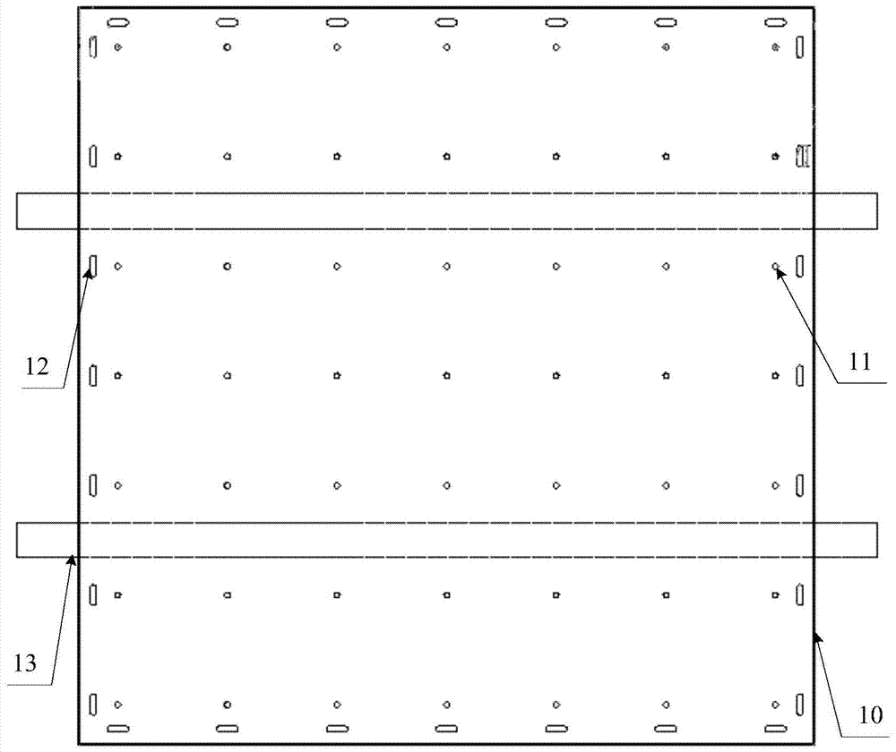
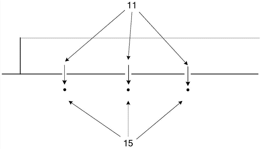
[0024] The invention discloses a mortar tray, which uses holes on the tray to locate the flow direction of the mortar (so that the mortar can flow according to a predetermined route), so as to ensure that each steel wire has a sufficient amount of mortar flow, so as to ensure a stable cutting force during the cutting process , so as to improve the working efficiency of the machine and ensure the product quality.

[0025] The following will clearly and completely describe the technical solutions in the embodiments of the present invention with reference to the accompanying drawings in the embodiments of the present invention. Obviously, the described embodiments are only some, not all, embodiments of the present invention. Based on the embodiments of the present invention, all other embodiments obtained by persons of ordinary skill in the art without making creative efforts belong to the protection scope of the present invention.

[0026] see Figure 1-Figure 3 , figure 1 A s...


PUM

PropertyMeasurementUnit
diameteraaaaaaaaaa

Abstract

The invention discloses a mortar tray. According to the mortar tray, the original mortar flowing manner is changed, and mortar flowing out of a mortar pipeline in a wire cutting machine flows into the mortar tray below the wire cutting machine firstly and then flows to steel wires from mortar holes in the fixed positions of the mortar tray, so that it can be ensured that each steel wire has the enough mortar flow so as to ensure that in the cutting process, the stable cutting force is obtained, the working efficiency of a machine table is improved, the product quality is ensured, the yield is improved, wire breaking is reduced, and meanwhile, happening of poor sizes is reduced; and non-directiveness of an original mortar system is changed into directiveness, so that management and control of the production process are facilitated, and due to a stable structure, the utilization rate of mortar can be improved, and the working efficiency is improved. The invention further discloses the wire cutting machine with the mortar tray. The non-directiveness of the original mortar system is changed into the directiveness, the management and control of the production process are facilitated; and due to the stable structure, the utilization rate of the mortar is improved, and the working efficiency is improved.

Description

technical field [0001] The invention relates to the technical field of wire cutting, in particular to a wire cutting machine and a mortar tray thereof. Background technique [0002] The mortar system of the existing wire cutting machine is a pipeline structure. The mortar is extracted from the mortar tank by the motor, and flows directly to the silicon ingots processed in the machine through the mortar pipe. The mortar flows to one point and then flows freely on the surface of the silicon block. flow. [0003] This system has obvious disadvantages: the mortar is directly hit on the silicon ingot, and the flow direction on the silicon ingot is determined by the topography of the silicon ingot. It cannot guarantee that all cutting steel wires can have a sufficient amount of mortar, and even the surface of the silicon ingot is uneven. The steel wire cannot be brought to the mortar, on the one hand, it is easy to cause wire breakage; on the other hand, the cutting force is unst...

Claims


Application Information

Patent Timeline
Patent Type & Authority Patents(China)
IPC IPC(8): B28D5/04
CPCB28D5/007B28D5/045
Inventor 程朝云叶钧刘小平黄英亮谢海涛徐志群金浩陈康平
Owner JINKO SOLAR CO LTD
Learn More