Connecting node for steel pipe concrete post and outside U-shaped steel and concrete composite beam

A technology for concrete-filled steel tubular columns and connecting nodes, which is applied to buildings, building structures, etc., can solve problems such as inability to apply outsourced U-shaped steel-concrete composite beams, a large number of openings, and failure to meet seismic requirements.

Inactive Publication Date: 2015-09-16
SHANDONG JIANZHU UNIV
View PDF5 Cites 11 Cited by
  • Summary
  • Abstract
  • Description
  • Claims
  • Application Information

AI Technical Summary

Problems solved by technology

[0014] (1) Since the bottom plate of the composite beam and the lower reinforced ring plate are lap welded, under the action of earthquake load, the weld seam is easy to crack and cannot meet the seismic requirements;
[0015] (2) Since the steel bars with negative bending moment all pass through the node area, there are many holes in the steel pipe wall, so the bearing capacity of the steel pipe is greatly weakened, and corresponding reinforcement measures need to be taken, such as repair welding steel plates, stiffeners, steel bars, etc. It not only increases the amount of steel used, but also increases the difficulty of construction;
[0016] (3) Since the side plate of the composite beam and the steel pipe wall are connected by welds, the on-site welding workload is large, which is not only laborious and time-consuming, but also the quality of the welds is difficult to guarantee, which is not conducive to the use of large-scale pr

Method used


Image

  • Connecting node for steel pipe concrete post and outside U-shaped steel and concrete composite beam
  • Connecting node for steel pipe concrete post and outside U-shaped steel and concrete composite beam
  • Connecting node for steel pipe concrete post and outside U-shaped steel and concrete composite beam

Examples


Embodiment Construction

[0050] In order to clearly illustrate the technical characteristics of this solution, the following will describe this solution through specific implementation modes and in conjunction with the accompanying drawings.

[0051] Limb cutting: refers to cutting off a part of the bottom plate of the U-shaped steel as required.

[0052] Composite beam: refers to the abbreviation of U-shaped steel concrete composite beam.

[0053] High-strength bolts: refer to high-strength bolts, which are a standard part. In general, high-strength bolts can withstand a larger load than ordinary bolts of the same specification.

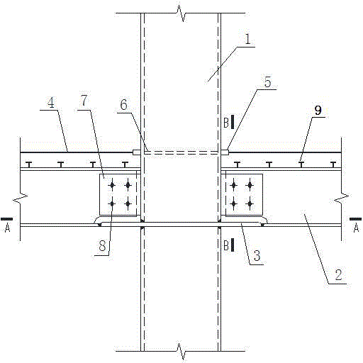
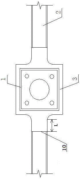
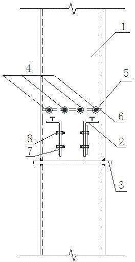
[0054] A connection node between a steel pipe concrete column and an outer U-shaped steel concrete composite beam, as shown in the figure, it includes a through partition 3 and a horizontal stiffening plate 6, and the through partition 3 and the horizontal stiffening plate 6 are respectively provided with pouring holes 12 and vent hole 13, guarantee the smooth progress of...


PUM

PropertyMeasurementUnit
Radiusaaaaaaaaaa

Abstract

The invention provides a connecting node for a steel pipe concrete post and an outside U-shaped steel and concrete composite beam. In order to prevent the lamellar tearing of the steel pipe walls and the outer surface deformation of a post wall plate, a penetrating separation plate penetrating through steel pipes is arranged in the steel pipes arranged in a position of a composite beam bottom plate; the steel pipes are broken in a position of the penetrating separation plate; the upper steel pipe and the lower steel pipe are connected with the upper end surface and the lower end surface of the penetrating separation plate through butt-jointed welding seams with grooves; a U-shaped steel bottom plate is connected with the penetrating separation plate by the butt-jointed welding seams after the amputation; the welding seams cannot easily crack; the connection intensity is high; and the anti-seismic performance is good. The two opposite ends of the steel pipes in the length direction of the composite beam are correspondingly provided with sleeves capable of being movably connected with the end parts of negative reinforcement steel bars; and the sleeves are welded with the outer walls of the steel pipes. The structural form has the advantages that the weakening on the carrying force of the steel pipes due to the hole forming in the side walls of the steel pipes can be reduced; meanwhile, the welding workload is reduced; the construction is convenient; and the assemblage can be conveniently realized. In order to effectively transfer the load, a horizontal reinforcement plate is fixedly welded in a position, corresponding to the sleeves, of an inner cavity of the steel pipes.

Description

technical field [0001] The invention relates to a concrete-filled steel pipe column and an outsourcing U-shaped steel-concrete composite beam, in particular to a connection node between a steel-pipe concrete column and an outsourcing U-shaped steel-concrete composite beam. Background technique [0002] Concrete-filled steel pipe column refers to the vertical member formed by filling concrete in the steel pipe. It has the advantages of high bearing capacity, good plasticity and ductility, high rigidity, convenient construction, and good fire resistance. It has received extensive attention from the engineering community in recent years. It is used more and more in multi-high-rise buildings and bridge engineering. According to different cross-sectional forms, CFST columns can be divided into circular CFST columns, rectangular CFST columns and polygonal CFST columns. Outer U-shaped steel-concrete composite beam is directly welded or cold-bent the steel plate into U-shaped steel...

Claims


Application Information

Patent Timeline
IPC IPC(8): E04B1/30E04B1/58
Inventor 林彦周学军苗纪奎
Owner SHANDONG JIANZHU UNIV
Why Eureka
Try Eureka