
A cooling device for high-temperature calcination production

A cooling device and high-temperature calcination technology, applied in the direction of processing discharged materials, waste heat treatment, furnaces, etc., can solve the problems of low heat exchange efficiency and low heat energy recovery rate, and achieve the effect of increasing heat exchange area

Active Publication Date: 2017-02-01
SHANDONG LUBEI ENTERPRISE GROUP +1
View PDF9 Cites 0 Cited by
  • Summary
  • Abstract
  • Description
  • Claims
  • Application Information

AI Technical Summary

Problems solved by technology

The indirect cooling equipment adopts indirect cooling, which can avoid dust emission, but it has the problems of low heat exchange efficiency and low heat recovery rate

Method used


Image

  • A cooling device for high-temperature calcination production
  • A cooling device for high-temperature calcination production
  • A cooling device for high-temperature calcination production

Examples


Embodiment 1

[0049] Example 1: Cooling 18~20t / h high temperature calcined a-alumina

[0050] The material temperature before cooling is 890 C°, the material volume is 18-20t / h, and the material temperature after cooling is <100 C°.

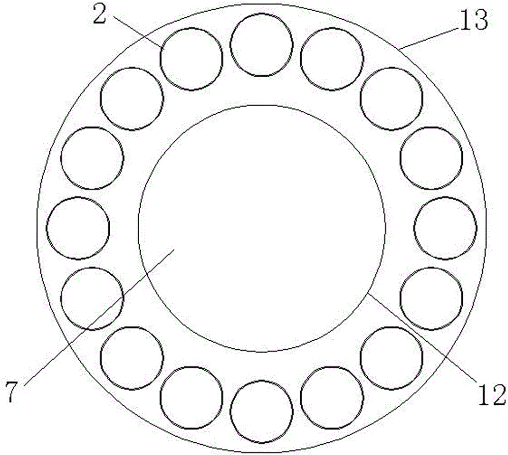
[0051] The specifications of the cooling cylinder: cylinder 13 diameter 3.6m*38m, material pipe 2 diameter 470mm, thickness 6mm, length 18000mm, quantity 18, single-layer distribution, material stainless steel, air duct 10 diameter 108mm, thickness 6mm, length 18000mm, quantity 100, double-layer distribution, material carbon steel, blower air volume 22500m3 / h.

[0052] Cylinder installation slope: 4%, cylinder speed: 4.23r / min.

[0053] Energy-saving effect of cooling device:

[0054] 1.23kj / kg. ℃×1000kg×(890℃-100℃)=971700 kj / t

[0055] 971700 kj / t×60%=583020 kj / t

[0056] Save 583020 kj of heat energy per hour.

Embodiment 2

[0057] Example 2: cooling 10t / h high temperature calcined a-alumina

[0058] The material temperature before cooling is 910 C°, the material volume is 10t / h, and the material temperature after cooling is <100 C°.

[0059] Cooling cylinder specifications: diameter 3.m*38m, material pipe 2 diameter 400mm, thickness 6mm, length 18000mm, quantity 16, single-layer distribution, material stainless steel, air duct 10 diameter 108mm, thickness 6mm, length 18000mm, quantity 80, Double-layer distribution, material carbon steel, blower air volume 15000m3 / h.

[0060] Cylinder installation slope: 4%, cylinder speed: 4.23r / min.

[0061] Energy-saving effect of cooling device:

[0062] 1.23kj / kg. ℃×1000kg×(910℃-100℃)=996300kj / t

[0063] 996300kj / t×60%=597780kj / t

[0064] Save 5977800kj of heat energy per hour.


PUM


Abstract

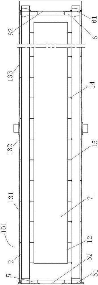
The invention belongs to the technical field of non-metallic material production equipment, and particularly relates to a cooling device for high-temperature calcination production. The cooling device comprises a cooling barrel (1) which comprises a primary cooling section (11) and a secondary cooling section (12), the primary cooling section (11) comprises a material pipe (2) and an air cavity (14), and the secondary cooling section (12) comprises an air pipe (10) and a material cavity (19). The cooling device has the advantages that the heat energy can be sufficiently recovered, and materials can be prevented from being brought into a rotary kiln for secondary overburning through cooling air.

Description

technical field [0001] The invention belongs to the technical field of non-metallic material production equipment, and in particular relates to a cooling device for high-temperature calcination production. Background technique [0002] At present, when non-metallic materials are processed, they usually need to be calcined at high temperature, such as alumina, titanium dioxide, etc., and generally need to be cooled after high temperature calcination. However, for some heat-sensitive powdery products that cannot be calcined twice, there is usually a problem that the cooling wind will bring the powdery products back to the kiln for secondary calcination during the cooling process. [0003] Taking a-alumina as an example, high-temperature calcined a-alumina, as a new type of environmentally friendly material, has become more and more widely used and its value has been soaring all the way. It has been praised and selected by people from all walks of life. Its uses are mainly in ...

Claims


Application Information

Patent Timeline
Patent Type & Authority Patents(China)
IPC IPC(8): F27D15/02F27D17/00
Inventor 吕天宝武文焕冯怡利武建民张荣安邱维志
Owner SHANDONG LUBEI ENTERPRISE GROUP
Learn More