A method for conductive connection of cables

A conductive connection and cable connection technology, applied in the direction of connection, circuit, electrical components, etc., can solve the problems of increased resistance, poor conductivity, inconvenient use, etc., and achieve reduced contact resistance, excellent electrical conductivity, and convenient use Effect

Active Publication Date: 2017-07-04
BEIJING EMIKON TECH DEV
View PDF5 Cites 0 Cited by
  • Summary
  • Abstract
  • Description
  • Claims
  • Application Information

AI Technical Summary

Problems solved by technology

Second, the contact surface will form an oxide film with poor conductivity in the air and adhere to the surface, increasing the resistance
Based on the new material of low-melting-point metal, low-melting-point metal conductive paste and conductive sheet have been developed. Both of them have good heat transfer effect, but they have the same problem of inconvenient use as traditional thermal conductive silicone grease.

Method used


Image

  • A method for conductive connection of cables

Examples


Embodiment 1

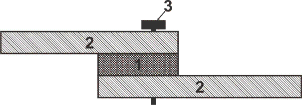
[0023] Embodiment 1 shows a typical application of the method for electrically conductive connection of cables in the present invention. figure 1 It is a schematic diagram of the application process of a method for conductive connection of cables in the embodiment. Among them: 1 is a cable, 2 is a low-melting point metal, and 3 is a fastening screw.

[0024] In this embodiment, fastening screws are used to fix the cables. The low-melting-point metal is indium-bismuth-tin alloy (the mass fraction of each component is In: 51.5%, Bi: 32%, Sn: 16.5%), and its melting point is 60°C.

[0025] When in use, after spraying molten low-melting point metal on the surface of the cable contact surface, fasten it with fastening screws. At this time, the low-melting-point metal is in rigid contact with the cable, and the air gap is large, so the contact resistance of the contact surface is large, and the heat generation is relatively large. When the temperature reaches the melting point of ...

Embodiment 2

[0027] figure 1 It is a schematic diagram of the application process of a method for conductive connection of cables in the embodiment. Among them: 1 is a cable, 2 is a low-melting point metal, and 3 is a fastening screw.

[0028] In this embodiment, fastening screws are used to fix the cables. The low-melting-point metal is indium-bismuth-tin-zinc alloy (the mass fraction of each component is In: 26%, Bi: 56%, Sn: 17%, Zn: 1%), and its melting point is 79°C.

[0029] When in use, after spraying molten low-melting point metal on the surface of the cable contact surface, fasten it with fastening screws. At this time, the low-melting-point metal is in rigid contact with the cable, and the air gap is large, so the contact resistance of the contact surface is large, and the heat generation is relatively large. When the temperature reaches the melting point of the low-melting-point metal, the low-melting-point metal melts and fills The air gap between the cables reduces the cont...


PUM


Abstract

Provided in the invention is a method for conductive connection of cables. The method is characterized in that cable connection parts are coated with melted low-melting-point metal; and the low-melting-point metal plays a role in conductive connection of cables. When the cables are fixed by fastening screws, the contact surfaces of the cables are coated with the melted low-melting-point metal and then the cables are fixed well by the fastening screws; and the low-melting-point metal and the cables are in hard contact at this time. During the first working process, the contact resistance between the cable contact surfaces is large and the heating value is relatively high; when the temperature reaches the melting point of the low-melting-point metal, the low-melting-point metal melts and the air gap between the cable contact surfaces is filled with the melted metal, thereby reducing the contact resistance and the heating value. When the cables are fastened in a screwing mode, the screwing fastening part only needs to be coated with the melted low-melting-point metal. The provided method that is designed ingeniously and can be implemented conveniently can be widely applied to the power and energy technical fields.

Description

technical field [0001] The invention relates to a method for conductive connection of cables, which uses a spraying process to spray low-melting point metals on the contact surfaces between cables, fills the air gap between the contact surfaces of the cables, and reduces contact resistance. Background technique [0002] Generally, there are two main reasons for contact resistance: first, due to the unevenness of the contact surface, the actual contact surface of the metal is reduced, and when the current flows through the conductor, the effective conductive interface of the contact surface is reduced. Second, the contact surface will form a layer of poorly conductive oxide film attached to the surface in the air, increasing the resistance. Excessive contact resistance is an important reason for the aging of the contact surface. The current mainstream methods to reduce contact resistance are: 1) Improve the material of the contact surface and improve the conductivity, such a...

Claims


Application Information

Patent Timeline
Patent Type & Authority Patents(China)
IPC IPC(8): H01R43/00H01R43/02
CPCH01R43/00H01R43/02H01R43/28
Inventor 郭瑞
Owner BEIJING EMIKON TECH DEV
Why Eureka
Try Eureka