Induction heating apparatus

An induction heating device and a technology to be heated, applied in the direction of induction heating device, induction heating, process efficiency improvement, etc., can solve the problems of inability to completely suppress the heating of the spiral copper tube and the reduction of magnetic flux, etc.

Active Publication Date: 2015-09-16
TOSHIBA MITSUBISHI-ELECTRIC IND SYST CORP
View PDF7 Cites 7 Cited by
  • Summary
  • Abstract
  • Description
  • Claims
  • Application Information

AI Technical Summary

Problems solved by technology

[0013] However, just by concentrating the magnetic flux on the end of the heated object as described above to obtain the improvement of the heating efficiency, there is a problem that it is impossible to completely suppress the

Method used


Image

  • Induction heating apparatus
  • Induction heating apparatus
  • Induction heating apparatus

Examples


no. 1 approach

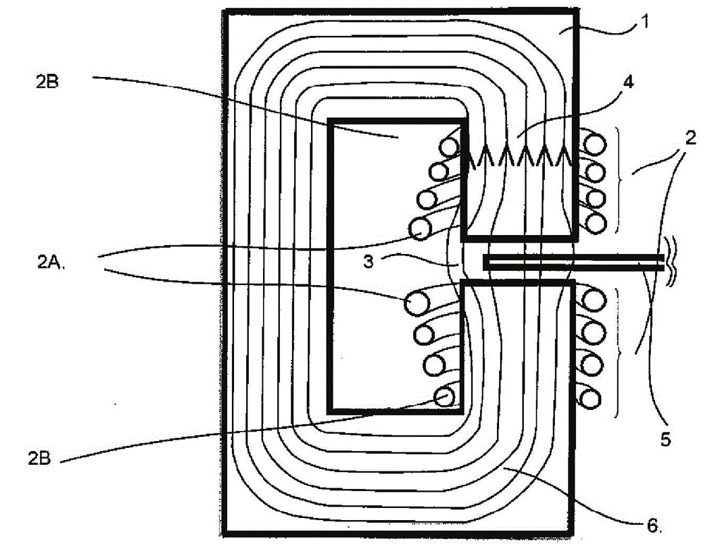
[0024] figure 1 It is a front view showing the induction heating device of the first embodiment of the present invention. Such as figure 1 As shown, a C-shaped iron core 1 is formed by laminating electromagnetic steel sheets, and spiral copper pipes 2 are respectively wound around the upper and lower core legs 4 sandwiching the opening 3 of the C-shaped iron core 1 to form an inductor. The spiral copper tube 2 is a heating coil. The end of the heated member 5 passes through the opening 3, and the heated member 5 is inductively heated by the magnetic flux 6 penetrating the inside of the C-shaped core 1 up and down to form a loop.

[0025] The induction heating device using the C-type inductor does not have a large air gap in the path of the magnetic flux 6, and has excellent heating efficiency.

[0026] Since the heated element 5 is a non-magnetic body exceeding the Curie point, the C-type inductor tends to expand greatly in the middle of the magnetic flux 6 passing through the open...

no. 2 approach

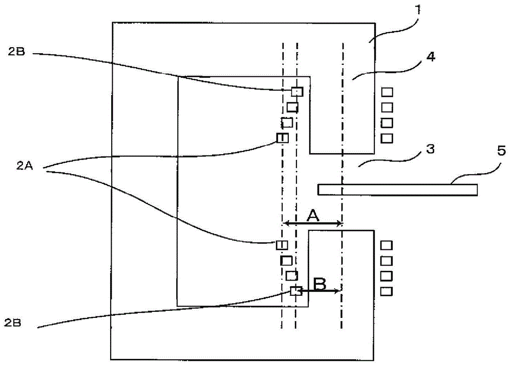
[0035] Next, the second embodiment will be described. Figure 5 It is a front view showing the induction heating device of the second embodiment of the present invention. Such as Figure 5 As shown, in the second embodiment, a heating coil, that is, a spiral copper tube 2 is wound around the upper and lower core legs 4 sandwiching the opening 3 of the C-shaped core 1, and the C-shaped inductor is formed in the C The upper and lower core legs 4 of the type inductor are respectively formed with inclined surfaces 4a on the end sides of the surfaces facing the openings 3 through which the heated material passes. The intervals between the openings 3 are enlarged toward the inside of the C-shaped core 1.

[0036] Inclined surfaces 4a are formed on the ends of the upper and lower core legs 4 facing the openings 3, and the gaps between the openings 3 are enlarged toward the inside of the C-shaped core 1, so that the magnetic flux 6 can easily flow between the upper and lower core legs. ...


PUM


Abstract

Provided is an induction heating apparatus of a C-shaped inductor, which can restrain spiral copper pipe heating, and magnetic flux reduction which is the reason of copper loss, and can not reduce the heating efficiency of the end portion of a heated piece. The induction heating apparatus is in pairs provided with fixed C-shaped inductors formed by C-shaped iron core structures at two end portions of a heat piece in the width direction, characterized in that the C-shaped inductor is composed of a main body iron core portion which is provided with an opening used for passing through a heated piece along the conveying direction of the heated piece; an iron core leg portion in connection with the opening portion and formed in a mode of clamping the opening portion up and down; and a heating coil which clamps the opening portion and winds the up and down iron core leg portion, allows linkage between the heated piece and magnetic flow so as to heat a piece to be heated, and is winded in a mode in which the winding diameter of the heating coil gradually expands towards the end portion of the surface opposite to the opening portion.

Description

[0001] This application is based on Japanese Patent Application No. 2014-048800 (application date: March 12, 2014), and enjoys priority benefits from this application. This application contains all the contents of the above application by referring to the above application. Technical field [0002] The invention relates to a C-type inductive induction heating device. Background technique [0003] In the hot rolling line for steel, after the heated material is heated to a predetermined temperature in advance, when the heated material is continuously conveyed, the heated material is formed into a state called a rough bar by a rough rolling mill, and then refined The rolling mill shapes the heated piece into a thin plate with the desired plate thickness and width. [0004] In the process of forming the heated member into a thin plate, there is a problem that the temperature of the widthwise end of the heated member gradually decreases. When the temperature drops and rolling is perfor...

Claims


Application Information

Patent Timeline
IPC IPC(8): H05B6/10
CPCY02P10/25H05B6/02
Inventor 桥本英二土斐崎哲嗣
Owner TOSHIBA MITSUBISHI-ELECTRIC IND SYST CORP
Why Eureka
Try Eureka