A frame hollow core tube structural system of a high-rise building

A technology for high-rise buildings and core tubes, applied in building components, building structures, buildings, etc., can solve the problems of core tubes with many shear walls, heavy weight, and poor economic efficiency, so as to increase building flexibility and reduce weight , the effect of reducing the cost

Active Publication Date: 2017-02-01
ARCHITECTURAL DESIGN RES INST OF GUANGDONG PROVINCE
View PDF5 Cites 0 Cited by
  • Summary
  • Abstract
  • Description
  • Claims
  • Application Information

AI Technical Summary

Problems solved by technology

[0007] Due to the fire protection requirements of high-rise structures in the old code, the plane area of ​​the frame-core tube structure cannot exceed 2000m 2 , and the fire compartment of the new code stipulates that the floor plan area can exceed 2000mm 2 , the floor area in actual engineering application is up to 3000m 2 Above, the floor area is large, and the area of ​​the core tube will also increase, resulting in too many shear walls in the core tube, the weight is too heavy, and the economy is not good

Method used


Image

  • A frame hollow core tube structural system of a high-rise building
  • A frame hollow core tube structural system of a high-rise building
  • A frame hollow core tube structural system of a high-rise building

Examples


Embodiment 1

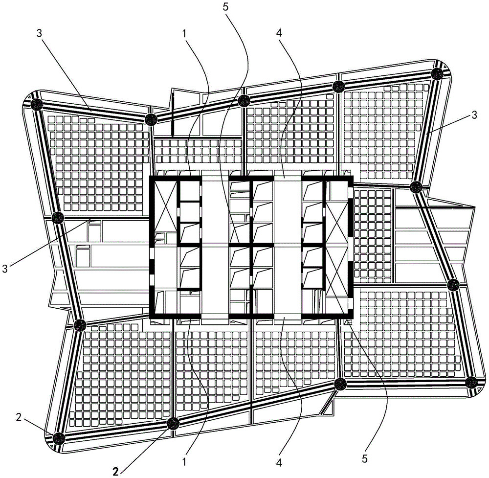
[0044] An embodiment of the frame hollow core tube structural system of a high-rise building of the present invention is as follows Figure 2 to Figure 5 As shown, the number of floors of a high-rise building is 50. The structural system includes shear walls 1, connecting beams 4, peripheral columns 2, frame beams 3 and floor slabs. The shear walls 1 are vertically arranged and located at the center of the high-rise building , the shear wall 1 is a plurality of pieces vertically arranged, and the connecting beam 4 is erected between the adjacent shear walls 1, and the shear wall 1 and the connecting beam 4 are surrounded to form a rectangular hollow core tube, and the peripheral columns 2 are located at At the periphery of the hollow core tube, the peripheral columns 2 are multiple vertically arranged steel pipe concrete columns, and the frame beams 3 are also multiple. Some frame beams 3 are erected between the peripheral columns 2 and the shear walls 1, and the remaining fram...

Embodiment 2

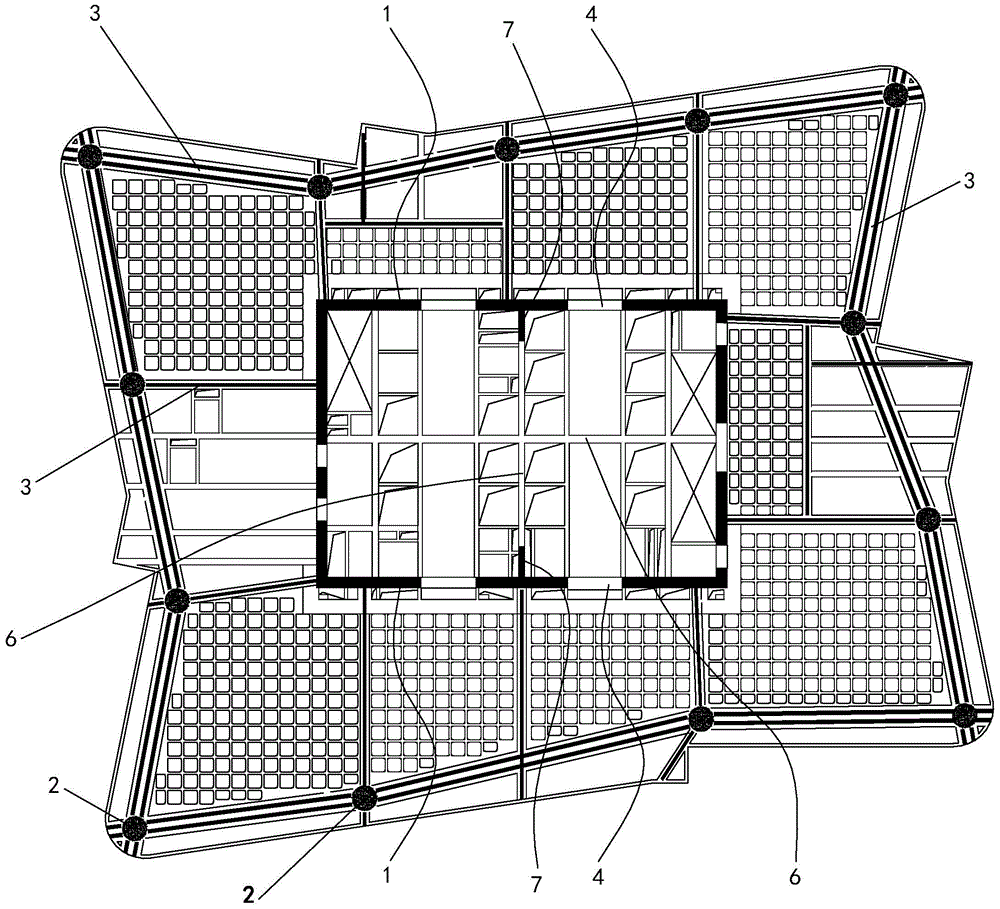
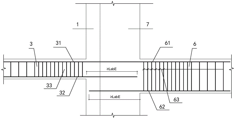
[0060] A second embodiment of the frame hollow core tube structural system of a high-rise building of the present invention is as follows Figure 6 to Figure 8As shown, the difference from Embodiment 1 is that there are four wall limbs 7 in this embodiment, which are respectively located on the four sides of the inner surface of the hollow core tube, and are symmetrically distributed around the center line of the hollow core tube. , the frame beams 3 on both sides of the wall 7, the inner beam 6 and the wall 7 are all located on the same straight line.


PUM


Abstract

The invention discloses a hollow core tube structure system of a high-rise building frame. The hollow core tube structure system comprises shear walls, connecting beams, peripheral columns, frame beams and a slab. The shear walls are arranged at the center of the high-rise building and are vertically arranged, the connecting beams are erected between the adjacent shear walls, the shear walls and the connecting beams enclose a hollow core tube, the peripheral columns are arranged on the periphery of the hollow core tube and are vertical steel pipe concrete columns, a part of the frame beams are erected between the peripheral columns and the shear walls, and the other frame beams are erected between the two adjacent peripheral columns. A plurality of inside-tube columns are arranged in the hollow core tube in a staggered manner, two ends of the inside-tube columns are overlapped on the shear walls respectively so as to reduce weight of the hollow core tube and reduce basic load and structural seismic force and manufacturing cost. The hollow core tube structure system can give the function of a second defense line of the peripheral columns into play.

Description

technical field [0001] The invention relates to a building structure, in particular to a frame hollow core tube structure system of a high-rise building. Background technique [0002] The shear wall cylinder is widely used in high-rise buildings because of its good lateral force resistance. The existing shear wall cylinder construction system of high-rise buildings is as follows: figure 1 As shown, including shear wall 1, connecting beam 4, peripheral column 2, frame beam 3, inner shear wall 5 and floor slab, shear wall 1 is vertically arranged at the center of a high-rise building, and shear wall 1 It is a multi-piece set vertically, and connecting beams 4 are erected between adjacent shear walls 1. The shear walls 1 and connecting beams 4 surround a hollow core tube, and the peripheral columns 2 are located on the periphery of the hollow core tube. The column 2 is a plurality of vertically arranged steel tube concrete columns, and the frame beam 3 is also a plurality of f...

Claims


Application Information

Patent Timeline
Patent Type & Authority Patents(China)
IPC IPC(8): E04B1/19E04B1/04E04B2/56E04B1/98
Inventor 陈星张小良林扑强龙秀海吴桂广焦柯杨代恒余银银陈航陈有德王仕琪李宁梁志红欧旻韬
Owner ARCHITECTURAL DESIGN RES INST OF GUANGDONG PROVINCE
Why Eureka
Try Eureka