Cooling exhaust pipe

A technology for exhaust pipes and coolers, which is applied in the direction of exhaust devices, noise reduction devices, engine components, etc., which can solve the problems of blocked components, difficult installation and maintenance, and increased costs, and achieve the goals of preventing damage, simple structure, and prolonging service life Effect

Active Publication Date: 2015-09-23
ZHEJIANG RICH LEO ENVIRONMENTAL TECH
View PDF5 Cites 1 Cited by
  • Summary
  • Abstract
  • Description
  • Claims
  • Application Information

AI Technical Summary

Problems solved by technology

[0002] The traditional exhaust structure of a car includes a purifier, a muffler and an air duct; the temperature of the exhaust gas discharged from the engine exhaust valve is as high as 600°C, and the high-temperature and high-pressure exhaust gas enters the purifier after being discharged from the exhaust valve, and then passes through multiple sets of mufflers After muffled, it is led out from the exhaust tailpipe; this exhaust pipe structure is more harmful to the purifier and muffler, and the high-temperature gas will accelerate the aging of the purifier and muffler, shortening the life of the exhaust pipe; in addition, the traditional exhaust pipe In order to ensure the noise reduction effect, the air pipe needs to be equipped with multiple sets of mufflers, which not only increases the cost, but also makes the exhaust pipe complicated and lengthy, making it difficult to install and maintain; the exhaust pipe is filtered and treated layer by layer. When the exhaust pipe is discharged, the temperature of the gas drops to about 70°C, and the water vapor in the exhaust gas cools down and forms water droplets. This is also one of the reasons why the traditional exhaust pipe sprays water. If the liquefied water droplets enter the muffler and purifier, it may be blocked. components, causing exhaust pipe failure

Method used


Image

  • Cooling exhaust pipe
  • Cooling exhaust pipe

Examples


Embodiment

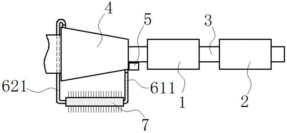
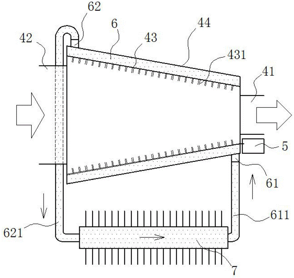
[0013] exist figure 1 , figure 2 In the shown embodiment, the cooling exhaust pipe includes a purifier 1, a muffler 2 and an air guide pipe 3; the purifier 1 and the muffler 2 are sequentially connected in series on the exhaust port of the engine by the air guide pipe 3 A cooler 4 is also connected in series between the exhaust port of the engine and the purifier 1; the cooler 4 is a tapered double-layer hollow tubular structure, and the aperture of the outlet end 41 of the cooler 4 is smaller than the inlet The aperture of the air end 42; the inner tube 43 of the cooler 4 is made of an elastic material, and the outer tube 44 is made of a hard material; on the inner wall of the inner tube 43, water-absorbing plush is also adhered Layer 431, the water-absorbing plush layer 431 stretches out of the outer tube 44 of the cooler 4 and stretches into a negative pressure liquid collection tank 5, and the water-absorbing plush layer 431 and the outer tube 44 reach an airtight state,...


PUM


Abstract

The invention relates to a cooling exhaust pipe. The cooling exhaust pipe comprises a purifier, a muffler and a gas guide pipe. A cooler is further connected between an engine and the purifier in series. The cooler is of a two-layer hollow pipe-shaped structure, an inner-layer pipe of the cooler is made of elastic materials, and an outer-layer pipe of the cooler is made of hard materials. An airtight annular-cylinder-shaped heat absorbing box is defined by the inner-layer pipe and the outer-layer pipe. The heat absorbing box is filled with cooling fluid. A fluid inlet hole and a fluid outlet hole which are communicated with the heat absorbing box and additionally provided with one-way valves are formed in the outer-layer pipe. The fluid inlet hole and the fluid outlet hole are provided with a fluid inlet pipe and a fluid outlet pipe respectively, and the fluid inlet pipe and the fluid outlet pipe are communicated with the two ends of a soft cooling box respectively. The exhaust pipe can quickly cool high-temperature tail gas, thereby effectively protecting the muffler and the purifier; meanwhile, liquefied water can be prevented from entering the muffler and the purifier, so the overall service life of the exhaust pipe is prolonged; besides, the exhaust pipe has an auxiliary muffling effect.

Description

technical field [0001] The invention relates to an automobile accessory, in particular to an exhaust pipe. Background technique [0002] The traditional exhaust structure of a car includes a purifier, a muffler and an air duct; the temperature of the exhaust gas discharged from the engine exhaust valve is as high as 600°C, and the high-temperature and high-pressure exhaust gas enters the purifier after being discharged from the exhaust valve, and then passes through multiple sets of mufflers After muffled, it is led out from the exhaust tailpipe; this exhaust pipe structure is more harmful to the purifier and muffler, and the high-temperature gas will accelerate the aging of the purifier and muffler, shortening the life of the exhaust pipe; in addition, the traditional exhaust pipe In order to ensure the noise reduction effect, the air pipe needs to be equipped with multiple sets of silencers, which not only increases the cost, but also makes the exhaust pipe complicated and...

Claims


Application Information

Patent Timeline
Patent Type & Authority Applications(China)
IPC IPC(8): F01N3/04
Inventor 陈伟强
Owner ZHEJIANG RICH LEO ENVIRONMENTAL TECH
Why Eureka
Try Eureka