Engine cooler

A cooling device and engine technology, which is applied in the direction of engine cooling, engine components, machines/engines, etc., can solve problems such as pistons and impact sounds, and achieve the effect of eliminating shaking sounds

Active Publication Date: 2015-09-23
KUBOTA LTD
View PDF14 Cites 3 Cited by
  • Summary
  • Abstract
  • Description
  • Claims
  • Application Information

AI Technical Summary

Problems solved by technology

[0006] "Problem" prone to piston slamming

Method used


Image

  • Engine cooler
  • Engine cooler
  • Engine cooler

Examples


Embodiment Construction

[0084] Figure 1 ~ Figure 4C It is a figure explaining the cooling apparatus of the engine which concerns on embodiment of this invention, In this embodiment, the cooling apparatus of a vertical inline two-cylinder diesel engine is demonstrated.

[0085] The schematic structure of this engine is as follows.

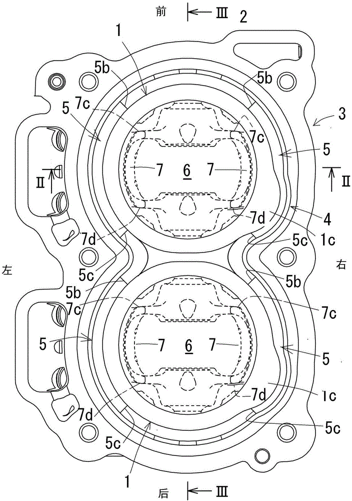
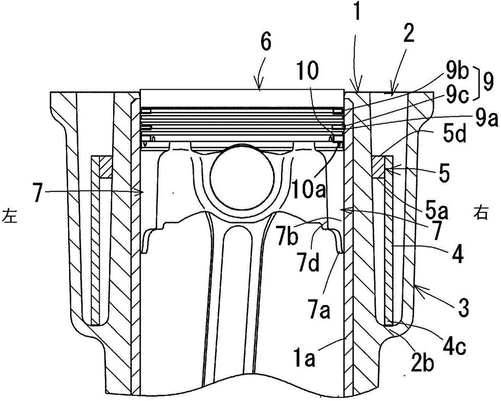
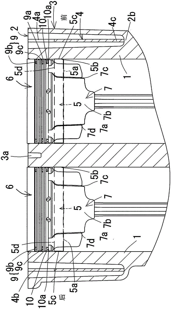
[0086] Such as Figure 1 ~ Figure 3 As illustrated, the engine has: a cylinder block 3 in which cylinder barrels 1 and 1 and a water cooling jacket 2 are built; a spacer 4 accommodated in the water cooling jacket 2 .

[0087] Such as figure 1 As illustrated, the water jacket 2 is formed around the cylinders 1, 1, and the spacer 4 surrounds the cylinders 1, 1 from the periphery.

[0088] The cylinder block 3 is made of aluminum castings, and iron cylinder liners are formed by casting the inner peripheral surfaces of the cylinder barrels 1 and 1 . The water-cooling jacket 2 has an open ceiling structure whose entire upper surface is open.

[0089] The outwardly bulging...


PUM


Abstract

An engine cooler capable of suppressing a piston slap sound is provided. The engine cooler includes a cylinder block 3 including a cylinder barrel 1, 1 and a water jacket 2, and a spacer 4 housed in the water jacket 2, the water jacket 2 surrounds the cylinder barrel 1, 1, and the spacer 4 encloses the cylinder barrel 1, 1. Given that a width direction of the cylinder block 3 is a lateral direction, a pressed member 5, 5 is pressed between the cylinder barrel 1, 1 and the spacer 4 on lateral sides of the cylinder barrel 1, 1, and a lower end 5a of the pressed member 5 is disposed above a lower end 7a of each of right and left skirts 7 of a piston 6 located at a top dead center.

Description

technical field [0001] The present invention relates to an engine cooling device, and more specifically, to an engine cooling device capable of reducing the generation of piston knocking sound. Background technique [0002] Conventionally, there is an engine cooling device including: a cylinder body in which a cylinder barrel and a water cooling jacket are built; and a spacer housed in the water cooling jacket. The water jacket is formed around the cylinder bore, and the spacer surrounds the cylinder bore from the periphery (for example, refer to Patent Document 1). [0003] According to such a cooling device, there is an advantage that the cooling state of the cylinder bore can be adjusted by restricting the flow of the cooling water in the water cooling jacket by the spacer. [0004] However, in the engine cooling device described in Patent Document 1, the upper surface of the water jacket adopts an open top plate structure with the entire surface open, so that the sound ...

Claims


Application Information

Patent Timeline
Patent Type & Authority Applications(China)
IPC IPC(8): F01P3/02F02F1/14
CPCF02F1/14F01P3/02F02F1/10F01P2003/021F02F1/16F02F2001/106
Inventor 长井健太郎小山秀行后藤英之山崎隆宽锹崎宽
Owner KUBOTA LTD
Why Eureka
Try Eureka