Solid-fuel internal combustion engine

A solid fuel, internal combustion engine technology, applied in the direction of internal combustion piston engine, combustion engine, powder engine fuel, etc., can solve problems such as failure to work normally, internal combustion engine damage, etc.

Inactive Publication Date: 2015-09-23
周虎
View PDF5 Cites 2 Cited by
  • Summary
  • Abstract
  • Description
  • Claims
  • Application Information

AI Technical Summary

Problems solved by technology

The main reason is that the combustion of solid fuel usually produces solid waste re

Method used


Image

  • Solid-fuel internal combustion engine
  • Solid-fuel internal combustion engine
  • Solid-fuel internal combustion engine

Examples


Embodiment 1

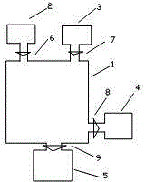
[0019] The invention consists of a combustion chamber 1, an air intake system 2, a feed system 3, a work system 4, and a slag discharge system 5. The combustion chamber 1 has a fixed volume, an igniter and a solid-gas separation device inside. The intake system 2 is connected to the combustion chamber 1 via an intake valve 6 . The feed system 3 is connected to the combustion chamber 1 through a feed valve 7 . The work system 4 is connected with the combustion chamber 1 through a work valve 8 . The slagging system 5 is connected with the combustion chamber 1 through the slagging valve 9 . Among them, the working system 4 is a multi-stage leveling working system, the air intake system 2 is an axial air compression system coaxially linked with the working system, the feeding system 3 is an independent electric slurry continuous feeding system, and the combustion chamber 1 is the inner wall High temperature resistant alloy combustion chamber with fireproof and heat insulating co...

Embodiment 2

[0021] The invention consists of a combustion chamber 1, an air intake system 2, a feed system 3, a work system 4, and a slag discharge system 5. The combustion chamber 1 has a fixed volume, an igniter and a solid-gas separation device inside. The intake system 2 is connected to the combustion chamber 1 via an intake valve 6 . The feed system 3 is connected to the combustion chamber 1 through a feed valve 7 . The work system 4 is connected with the combustion chamber 1 through a work valve 8 . The slagging system 5 is connected with the combustion chamber 1 through the slagging valve 9 . Among them, the work system 4 is a multi-stage leveling work system, the intake system 2 is a multi-stage axial flow air compression system coaxially linked with the work system, the feeding system 3 is an independent electric slurry continuous feeding system, and the combustion chamber 1 It is a high-temperature-resistant alloy combustion chamber with a fireproof and heat-insulating coating...

Embodiment 3

[0023] The invention consists of a combustion chamber 1, an air intake system 2, a feed system 3, a work system 4, and a slag discharge system 5. The combustion chamber 1 has a fixed volume, an igniter and a solid-gas separation device inside. The intake system 2 is connected to the combustion chamber 1 via an intake valve 6 . The feed system 3 is connected to the combustion chamber 1 through a feed valve 7 . The work system 4 is connected with the combustion chamber 1 through a work valve 8 . The slagging system 5 is connected with the combustion chamber 1 through the slagging valve 9 . Among them, the work system 4 is a multi-stage leveling work system, the intake system 2 is a multi-stage axial flow air compression system coaxially linked with the work system, the feeding system 3 is an independent electric slurry continuous feeding system, and the combustion chamber 1 It is a high-temperature-resistant alloy combustion chamber with a fireproof and heat-insulating coating...


PUM


Abstract

The invention discloses a solid-fuel internal combustion engine. The solid-fuel internal combustion engine consists of a combustion chamber, an air inlet system, a feeding system, a working system and a slag discharging system, wherein the air inlet system is connected with the combustion chamber, and is responsible for supplying compressed air to the combustion chamber; the feeding system is connected with the combustion chamber, and is responsible for conveying solid fuel to the combustion chamber; the size of the combustion chamber is constant; the solid fuel is continuously combusted in the combustion chamber, high-temperature high-pressure gas and solid waste slags are generated; the working system is connected with the combustion chamber, and the working system converts the internal energy of the high-temperature high-pressure gas into mechanical energy to be output outsides; the slag discharging system is connected with the combustion chamber, and is responsible for discharging the waste slags generated in the combustion chamber out of the internal combustion engine.

Description

technical field [0001] The present invention relates to an internal combustion engine, in particular to a solid fuel internal combustion engine. Background technique [0002] The fuel of general internal-combustion engine burns in the working cylinder, pushes the piston to do work externally, the fuel of internal-combustion engine can only be liquid fuel or gaseous fuel, can not use solid fuel. The main reason is that the combustion of solid fuel usually produces solid waste residue, which causes damage to the internal combustion engine and cannot work normally. Contents of the invention [0003] The object of the present invention is to provide an internal combustion engine which can use solid fuel. The invention consists of a combustion chamber, an air intake system, a feed system, a work system and a slag discharge system. The air intake system is connected to the combustion chamber and is responsible for delivering compressed air to the combustion chamber. The feed ...

Claims


Application Information

Patent Timeline
IPC IPC(8): F02B45/02
CPCY02T10/30
Inventor 周虎周思齐
Owner 周虎
Why Eureka
Try Eureka