A flue water reverse circulation recovery heat energy furnace

A cyclic recovery and flue technology, applied in water heaters/stoves, household heating, household heating, etc., can solve the problems of large water heating area, waste of energy, and unsuitable for hot water to be used immediately. The effect of reasonable heating and effective use of heat

Active Publication Date: 2017-08-22
BENGBU KUNPENG FOOD & BEVERAGE
View PDF6 Cites 0 Cited by
  • Summary
  • Abstract
  • Description
  • Claims
  • Application Information

AI Technical Summary

Problems solved by technology

[0002] At present, the heating furnaces used in rural areas of our country are generally equipped with water jackets, and a multi-circulation flue is formed in the water jacket, which is to surround the flue with water for heating. The water heating area is large and there is a lot of water storage. This kind of furnace is suitable for heating in winter. , not suitable for instant hot water use at ordinary times. When heating is not needed, because the water jacket has a lot of water, when hot water is needed, the entire water jacket needs to be heated to increase the water temperature, which is a waste of energy.

Method used


Image

  • A flue water reverse circulation recovery heat energy furnace
  • A flue water reverse circulation recovery heat energy furnace
  • A flue water reverse circulation recovery heat energy furnace

Examples


Embodiment 1

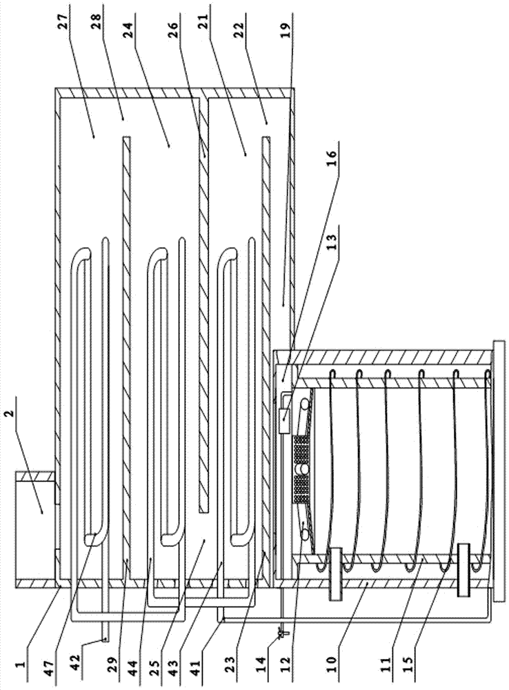
[0028] Embodiment 1: as figure 1 As shown: this embodiment 1 includes a heating furnace, a heating box 1 connected to the flue of the heating furnace, and a chimney 2 connected to the heating box 1; a heating chamber is arranged in the heating box 1, and a detour water pipe 4 is arranged in the heating chamber ; Detour water pipe 4 is a detour setting. The flue of the heating furnace is arranged circuitously in the heating box 1, and its path is a continuous broken line. The detour water pipe 4 includes a first detour pipe 43, a second detour pipe 44 and a third detour pipe 47; a partition A23 and a partition C29 are arranged on one side of the heating box 1, and on the other side of the heating box 1 A partition B26 is arranged on the top; the partition A23 is arranged below the partition B26, and the partition C29 is arranged above the partition B26; between the partition A23 and the bottom plate of the heating box 1 is a heat inlet channel 19; between the partition A23 Be...

Embodiment 2

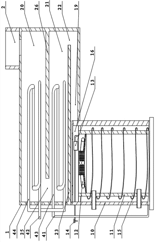
[0032] Embodiment 2: as figure 2 As shown: this embodiment 2 includes a heating furnace, a heating box 1 communicating with the flue of the heating furnace, and a chimney 2 communicating with the heating box 1; a heating chamber is arranged in the heating box 1, and a circuitous water pipe 4 is arranged in the heating chamber ; Detour water pipe 4 is a detour setting. The flue of the heating furnace is arranged in a detour in the heating box 1 .

[0033] The detour water pipe 4 comprises a first detour pipe 43 and a second detour pipe 44; a partition A23 is arranged on one side plate of the heating box 1; a partition B26 is provided on the other side board of the heating box 1; The heating chamber A21 is formed between A23, the partition B26 and the two side plates of the heating box 1; the heating chamber b20 is formed between the partition B26, the top plate of the heating box 1 and the two side plates of the heating box 1; between the partition A23 and the corresponding Th...


PUM


Abstract

The invention relates to a flue water reverse circulation recovery heat energy furnace which comprises a heating furnace, a heating box and a chimney. A roundabout water pipe is arranged in a roundabout winding manner; a flue path is a continuous folding line; a water inlet of the roundabout pipe is lower than a water outlet; the heating furnace comprises a furnace wall, a hearth and a heating furnace flue; a heat inlet channel is communicated with the heating furnace flue; the hearth is sleeved with a hearth spiral pipe; and the heating furnace flue is internally provided with a heat insulation box and a combustion supporting sleeve. According to the furnace, the roundabout water pipe is heated sufficiently; heat is made full use of; the dust is reduced; an environment is protected; the heating is reasonable; hot water is used when heated; and combustibles are sufficiently burnt.

Description

technical field [0001] The invention relates to a hot water heater for recycling heat energy, in particular to a heat energy furnace for reverse circulation recycling of flue water. Background technique [0002] At present, the heating furnaces used in rural areas of our country are generally equipped with water jackets, and a multi-circulation flue is formed in the water jackets, and the flue is surrounded by water for heating. The water heating area is large and there is a lot of water storage. This kind of furnace is suitable for heating in winter. , It is not suitable for hot water to be used immediately. When heating is not needed, because the water jacket has a lot of water, when hot water is needed, the entire water jacket needs to be heated before the water temperature can go up, wasting energy. Contents of the invention [0003] The technical problem to be solved by the present invention is to provide a flue water reverse circulation recovery heat energy furnace w...

Claims


Application Information

Patent Timeline
Patent Type & Authority Patents(China)
IPC IPC(8): F24C1/00F24C13/00F24C15/00
CPCF24C13/00F24C15/00
Inventor 路泽民
Owner BENGBU KUNPENG FOOD & BEVERAGE
Why Eureka
Try Eureka