
Calibration device and method of ultra-high frequency partial discharge sensor

A partial discharge and calibration device technology, which is applied to measurement devices, instruments, measuring electrical variables, etc., can solve the problems of cumbersome process, aliasing of different spectrums, and difficult evaluation of calibration results, achieve accurate bandwidth and sensitivity, and reduce workload. Effect

Active Publication Date: 2015-09-23
SHENZHEN POWER SUPPLY BUREAU +1
View PDF5 Cites 9 Cited by
  • Summary
  • Abstract
  • Description
  • Claims
  • Application Information

AI Technical Summary

Problems solved by technology

However, currently there are no relevant international / national / industry standards for UHF partial discharge sensors, so there is no uniform standard for assessment and verification of UHF partial discharge sensors from different manufacturers in the market
Although the International Large Power Grid Conference once proposed the method of artificial pulse injection to calibrate the sensitivity and bandwidth of the UHF partial discharge sensor, it needs repeated debugging to determine a reasonable artificial pulse. The process is cumbersome, and because the artificial pulse includes Abundant spectrum components easily lead to aliasing of different spectrums, making it difficult to evaluate calibration results

Method used


Image

  • Calibration device and method of ultra-high frequency partial discharge sensor
  • Calibration device and method of ultra-high frequency partial discharge sensor

Examples


Embodiment Construction

[0027] In order to make the object, technical solution and advantages of the present invention clearer, the present invention will be further described in detail below in conjunction with the accompanying drawings.

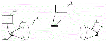
[0028] Such as figure 1 As shown, in the embodiment of the present invention, a calibration device for an ultra-high frequency partial discharge sensor is proposed, which cooperates with the ultra-high frequency partial discharge sensor L to be calibrated, and the device includes a signal generator for providing an ultra-high frequency signal 1. Signal receiver for receiving UHF signals 2. Impedance transition section for eliminating refraction and reflection of UHF signals 3. Coaxial transmission line for generating TEM waves during UHF signal transmission 4. Matching Impedance 5 and an oscilloscope 6 for displaying TEM wave frequency and amplitude; wherein,

[0029] There are two impedance transition sections 3, and the two impedance transition sections 3 are c...


PUM


Abstract

The invention provides a calibration device and method of an ultra-high frequency partial discharge sensor. The calibration device and method are matched with an ultra-high frequency partial discharge sensor to be calibrated. The calibration device includes a signal generator for providing ultra-high frequency signals, a signal receiver for receiving the ultra-high frequency signals, impedance transition sections for eliminating ultra-high frequency signal refraction and reflection, a coaxial transmission line used for generating TEM waves when the ultra-high frequency signals are transmitted, a matching impedor and an oscilloscope for displaying the frequency and amplitude of the TEM waves; two impedance transition sections exist and are circular cone-shaped; the top parts of the circular cone-shaped structures of the two impedance transition sections are provided with the matching impedor and the signal receiver connected with the signal generator respectively; the coaxial transmission line is arranged between the bottoms of the circular cone-shaped structures of the two impedance transition sections; the coaxial transmission line is a hollow circular cylinder; and the inner wall of the coaxial transmission line is provided with the ultra-high frequency partial discharge sensor to be calibrated which is connected with the oscilloscope. With the calibration device provided by the embodiment of the invention adopted, the sensitivity and bandwidth of the ultra-high frequency partial discharge sensor can be calibrated more accurately, and workload can be reduced.

Description

technical field [0001] The invention relates to the technical field of ultra-high frequency partial discharge sensors, in particular to a calibration device and method for ultra-high frequency partial discharge sensors. Background technique [0002] UHF partial discharge detection technology has been widely used in the on-line monitoring of insulation status of large power equipment such as GIS (Gas Insulated Switchgear, gas insulated switchgear) due to its strong anti-interference ability and other advantages. However, currently there are no relevant international / national / industry standards for UHF partial discharge sensors, so there is no uniform standard for assessment and verification of UHF partial discharge sensors from different manufacturers in the market. Although the International Large Power Grid Conference once proposed the method of artificial pulse injection to calibrate the sensitivity and bandwidth of the UHF partial discharge sensor, it needs repeated debug...

Claims


Application Information

Patent Timeline
Patent Type & Authority Applications(China)
IPC IPC(8): G01R35/00
Inventor 张欣黄荣辉向真姚森敬庞磊张乔根文韬秦逸帆
Owner SHENZHEN POWER SUPPLY BUREAU
Learn More