SOP element positioning and defect detecting method based on vision

A defect detection and component technology, applied in image data processing, instruments, calculations, etc., can solve problems such as insufficient precision and sensitivity to changes in the external environment

Active Publication Date: 2015-09-23
宁波智能装备研究院有限公司
View PDF5 Cites 20 Cited by
  • Summary
  • Abstract
  • Description
  • Claims
  • Application Information

AI Technical Summary

Problems solved by technology

[0005] The present invention aims to solve the problem that the accuracy of SOP components is not enough when they are mounted on a placement machine and is sensitive to changes in the external environment, and provides a visual positioning and positioning system for SOP components that has good real-time performance and is applicable to many types of SOP components. Methods for Visual Defect Detection

Method used


Image

  • SOP element positioning and defect detecting method based on vision
  • SOP element positioning and defect detecting method based on vision
  • SOP element positioning and defect detecting method based on vision

Examples


specific Embodiment approach 1

[0052] Specific embodiment one: a kind of vision-based SOP component location and defect detection method of the present embodiment, it realizes according to the following steps:

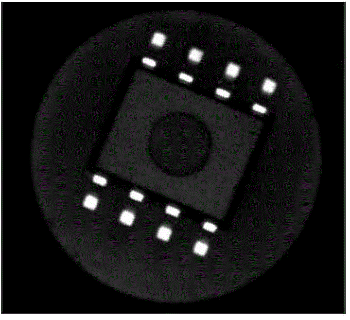
[0053] 1. Check whether the image in the selected area meets the brightness requirements;

[0054] (1) Scan all the image pixels in the selected area, and record the total number of image pixels as s 1 , the number of pixels whose gray value is greater than 150 is recorded as s 2 ;

[0055] (2) Take the ratio r 1 =0.03, r 2 =0.90, if s 1 / s 2 1 image area is too dark, if s 1 / s 2 >r 2 If the image area is too bright, stop and return the corresponding error code; otherwise, continue to the next step;

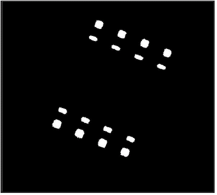
[0056] 2. Binarize the image of the selected area to obtain a binarized image;

[0057] The second step is specifically:

[0058] (1) The first method is to manually input a fixed threshold value binarization method, that is, the input threshold value is T, when the pixel value t of the i-th...

specific Embodiment approach 2

[0082] Specific implementation mode two: the difference between this implementation mode and specific implementation mode one is: the step four is specifically:

[0083] The main purpose is to deal with the following two types of outer boundary point sets: one is due to the redundant outer boundary point sets generated when the threshold selection of the second step binarization process is too low, it is necessary to remove such outer boundary point sets; the other is due to There are internal and nested relationships between some boundaries, and the relationship between such outer boundary point sets needs to be clarified;

[0084] 1) Take the outer boundary point set of a certain binarized image obtained in the third step, and require that the number of points contained in it must be greater than 10, otherwise directly remove the outer boundary point set;

[0085] 2) Check whether each outer boundary point set of the binarized image has an inner or nested outer boundary point ...

specific Embodiment approach 3

[0090] Specific implementation mode three: the difference between this implementation mode and specific implementation modes one or two is that the step five is specifically:

[0091] Use the bubble sorting method to sort each boundary point set in the fourth step according to the size of the area surrounded by the boundary from small to large;

[0092] 1) Calculate the average value of the area of ​​the three boundary point sets in the middle and denote it as a;

[0093] 2) In turn, the area a surrounded by each boundary point set i Compare with a, keep a i i >0.6*a boundary point set i; where, the a i is the area of ​​the i-th boundary point set.

[0094] Other steps and parameters are the same as those in Embodiment 1 or Embodiment 2.


PUM


Abstract

The invention discloses an SOP element positioning and defect detecting method based on vision, and relates to visual positioning and visual defect detecting of an SOP element in a surface mount technology visual system. For solving the problem that the SOP element is insufficient in precision and sensitive to the external environment change when being used for the mounting of a chip mounter, the invention provides a SOP element positioning and defect detecting method based on vision. The method comprises the following steps: checking whether a selected region image meets a luminance requirement; binarizing the selected region image to obtain a binarized image; extracting an outer boundary outline of the binarized image obtained in the second step through the adoption of a canny edge detection extracting method to obtain each outer boundary point set of the binarized image; performing SOP element pin defect detection according to above obtained data. The method is applied to the visual field of the chip mounter.

Description

technical field [0001] The invention relates to a visual inspection method for SOP components in a surface assembly technology (SMT) visual system, and mainly realizes the visual positioning and visual defect detection functions of the SOP components. Background technique [0002] With the development of the electronics industry, Surface Mount Technology (SMT, Surface Mount Technology) also develops rapidly. Among them, the placement machine is the key equipment on the SMT production line, which mainly realizes the assembly of SMT components. High-performance placement machines generally use machine vision systems, which are one of the most critical systems for placement machines, and their performance directly affects the placement accuracy and speed of placement machines. [0003] For a mature chip mounter vision system, the research and demonstration of the component visual recognition method is very important. This is the basic problem of the chip mounter vision system....

Claims


Application Information

Patent Timeline
Patent Type & Authority Applications(China)
IPC IPC(8): G06T7/00
CPCG06T7/0004G06T2207/30141
Inventor 高会军王毅孙昊白立飞杨宪强张延琪张天琦周纪强
Owner 宁波智能装备研究院有限公司
Why Eureka
Try Eureka